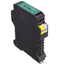
AS-Interface safety module VBA-4E2A1A-KE3-ZEL/E2L/SEL
- Safety output module with diagnostic node and I/O node
- 1 enabling circuit with 2 safe electronic outputs
- Assigns a complete address and two A/B addresses
- 1st A/B address: 3 standard inputs and 1 EDM input (I/O node)
- 2nd A/B address: diagnostics and operational switching of the safe outputs (diagnostic node)
- Applications up to category 4/PL e/SIL 3
Please note: All product-related documents, such as certificates, declarations of conformity, etc., which were issued prior to the conversion under the name Pepperl+Fuchs GmbH or Pepperl+Fuchs AG, also apply to Pepperl+Fuchs SE.
Download the complete datasheet as a PDF:
Datasheet excerpt: Technical data of VBA-4E2A1A-KE3-ZEL/E2L/SEL
| Product Description |
|---|
| KE3 switch cabinet module, 1 safety-related electronic output, 4 standard inputs, 2 standard outputs |
| General specifications | ||
|---|---|---|
| Node type | A/B node, standard node | |
| AS-Interface specification | V3.0 | |
| Required gateway specification | ≥ V2.1 | |
| Functional safety related parameters | ||
| Safety Integrity Level (SIL) | SIL 3 | |
| Performance level (PL) | PL e | |
| Mission Time (TM) | 20 a | |
| PFHd | 1.91 E-9 | |
| PFD | 5.94 E-7 | |
| Indicators/operating means | ||
| LED FAULT | error display; LED red red: communication error |
|
| LED PWR | AS-Interface voltage; LED green | |
| LED IN | switching state (input); 4 LED yellow | |
| LED OUT | For flashing patterns see diagnostics table | |
| Electrical specifications | ||
| Auxiliary voltage (input) | 24 V ± 20 % PELV | |
| Rated operating voltage | 26.5 ... 31.6 V from AS-Interface | |
| Rated operating current | < 200 mA | |
| Protection class | III | |
| Surge protection | UEXT, Ue: Over voltage category III, safe isolated power supplies (PELV) | |
| Input | ||
| Number/Type | 3 standard inputs, 1 EDM input | |
| Supply | from external auxiliary voltage UAUX | |
| Voltage | 24 V DC | |
| Input current | Static switching current: 4 mA at 24 V. Dynamic switching current: 15 mA at 24 V (T=100 μs) | |
| Sensor supply | ≤ 100 mA | |
| Output | ||
| Number/Type | 2 output switch elements Max contact load: 0.5 A DC-13 at 30 V 1 safe electronic output |
|
| Supply | from external auxiliary voltage UAUX | |
| Directive conformity | ||
| Electromagnetic compatibility | ||
| Directive 2014/30/EU | EN 62026-2:2013 EN 61000-6-2:2005/AC:2005 EN 61000-6-3:2007/A1:2011 |
|
| Standard conformity | ||
| Electromagnetic compatibility | EN 61326-3-1:2008 | |
| Degree of protection | EN 60529:2000 | |
| Electrical safety | EN ISO 13849-1:2008 EN ISO 13849-2:2012 | |
| Emitted interference | EN 61000-6-3:2007/A1:2011 | |
| AS-Interface | EN 62026-2:2013 | |
| Noise immunity | EN 61000-6-2:2005/AC:2005 EN 62026-2:2013 | |
| Functional safety | IEC 61508:2010 (SIL3) EN 62061:2005 | |
| Programming instructions | ||
| Profile | Diagnostic node: S-7.A.E, ID1 = 5 Input node: S-7.A.E, ID1 = 7 |
|
| IO code | 7 | |
| ID code | F | |
| Ambient conditions | ||
| Ambient temperature | 0 ... 55 °C (32 ... 131 °F) | |
| Storage temperature | -25 ... 85 °C (-13 ... 185 °F) | |
| Mechanical specifications | ||
| Degree of protection | IP20 | |
| Connection | removable terminals rated connection capacity: rigid/flexible (with and without wire-end ferrules): 0.25 mm2 ... 2.5 mm2 for multiple-wire connection with two wires of equal cross-section: flexible with twin wire-end ferrules: 0.5 mm2 ... 1.5 mm2 |
|
| Material | ||
| Housing | PA 66-FR | |
| Dimensions | ||
| Height | 99 mm | |
| Width | 22.5 mm | |
| Length | 107 mm | |
| Mounting | DIN mounting rail | |
Classifications
| System | Classcode |
|---|---|
| ECLASS 13.0 | 27272603 |
| ECLASS 12.0 | 27242604 |
| ECLASS 11.0 | 27242604 |
| ECLASS 10.0.1 | 27242604 |
| ECLASS 9.0 | 27242604 |
| ECLASS 8.0 | 27242604 |
| ECLASS 5.1 | 27242604 |
| ETIM 9.0 | EC001599 |
| ETIM 8.0 | EC001599 |
| ETIM 7.0 | EC001599 |
| ETIM 6.0 | EC001599 |
| ETIM 5.0 | EC001599 |
| UNSPSC 12.1 | 39121535 |
Details: VBA-4E2A1A-KE3-ZEL/E2L/SEL
Function
The AS-Interface safety output module VBA-4E2A1A-KE3-ZEL/E2L/SEL is a control cabinet module with two safe electronic outputs. The outputs are dependent on a common safe release circuit, but they can be switched separately from each other by conventional output bits as long as the release from the safety monitor is present. In addition, the module has an A/B node for diagnostics and a second A/B node for the connection of three conventional inputs and the contactor feedback circuit EDM.
The housing is only 22.5 mm wide and takes up little space in the switch cabinet. A snap-on function mounts the module onto the 35 mm mounting strip in line with EN 50022.
An addressing socket is integrated into the module. Access to the addressing of the safe output and the integrated A/B nodes is done by switching the programming switches.
The connection is made via plug-in terminals. Four-way (black) terminal blocks are used for the inputs. The AS-Interface is connected via a two-way terminal block (yellow). This allows the sensors or the power supply to be easily separated for commissioning or service. Power is supplied to the inputs and connected sensors by an external auxiliary power supply. Yellow LEDs display the current switching status of the inputs and outputs. The red LED FAULT displays communication errors and indicate that the A0 output bit is set. A green LED ASI displays the operating voltage and the address 0.
Product Documentation: VBA-4E2A1A-KE3-ZEL/E2L/SEL
| Brief Instructions | Language | File Type | File Size |
|---|---|---|---|
| Mounting Instruction VBA-4E2A1A-KE3-ZEL/E2L/SEL / Montageanleitung VBA-4E2A1A-KE3-ZEL/E2L/SEL | ALL | 1394 KB | |
| Safety and Security Documentation | |||
| Instruction Manual VBA-4E2A1A-KE3-ZEL/E2L/SEL / Betriebsanleitung VBA-4E2A1A-KE3-ZEL/E2L/SEL | ALL | 443 KB | |
| Manuals | |||
| Manual VBA-4E2A1A-KE3-ZEL/E2L/SEL | ENG | 3543 KB | |
Design / Simulation: VBA-4E2A1A-KE3-ZEL/E2L/SEL
| CAD | Language | File Type | File Size |
|---|---|---|---|
| CAD 3-D / CAD 3-D | ALL | STP | 4525 KB |
| CAD Portal / CAD Portal | ALL | LINK | --- |
| CAE | |||
| CAE EPLAN Data Portal / CAE EPLAN Data Portal | ALL | LINK | --- |
| CAE EPLAN macro EDZ / CAE EPLAN Makro EDZ | ALL | EDZ | 1058 KB |
Approvals: VBA-4E2A1A-KE3-ZEL/E2L/SEL
| Certificates | Certificate No. | Language | File Type | File Size |
|---|---|---|---|---|
| US CA UL | E223772 | ALL | LINK | --- |
Software: VBA-4E2A1A-KE3-ZEL/E2L/SEL
| Software Tools | Release Info | File Type | File Size |
|---|---|---|---|
| SISTEMA SLB Library AS-Interface Safety / SISTEMA SLB Library AS-Interface Safety | ZIP | 622 KB |
Associated Products: VBA-4E2A1A-KE3-ZEL/E2L/SEL
| Accessories | ||||||
|---|---|---|---|---|---|---|
|
||||||
|
||||||
|
||||||


 +44 161 6336431