Serviceline Industriële Sensoren
Serviceline Explosiebeveiliging

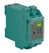
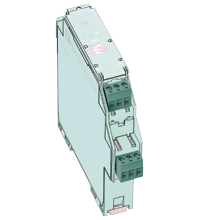
Temperature Converter with Trip Values KFD2-GUT-1.D

KFD2-GUT-1.D
  • 1-channel signal conditioner
  • 24 V DC supply (Power Rail)
  • Thermocouple, RTD, potentiometer or voltage input
  • Redundant TC input
  • Current output 0/4 mA ... 20 mA
  • 2 relay contact outputs
  • Configurable by PACTware or keypad
  • Line fault (LFD) and sensor burnout detection
  • Up to SIL 2 acc. to IEC/EN 61508 / IEC/EN 61511

Please note: All product-related documents, such as certificates, declarations of conformity, etc., which were issued prior to the conversion under the name Pepperl+Fuchs GmbH or Pepperl+Fuchs AG, also apply to Pepperl+Fuchs SE.

De complete datasheet als PDF downloaden:


Technische gegevens  KFD2-GUT-1.D

General specifications
Signal typeAnalog input
Functional safety related parameters
Safety Integrity Level (SIL)SIL 2
Supply
Connectionterminals 23+, 24- or power feed module/Power Rail
Rated voltage20 ... 30 V DC
Rated currentapprox. 100 mA
Power dissipation/power consumption≤ 2 W / 2.2 W
Interface
Programming interfaceprogramming socket
Input
Connection sidefield side
Connectionterminals 1, 2, 3, 4, 6
RTDPt100, Pt500, Pt1000, Ni100, Ni1000
Measuring currentapprox. 400 µA
Types of measuring2-, 3-, 4-wire technology
Lead resistancemax. 50 Ω
Measurement loop monitoringsensor breakage, sensor short-circuit
Thermocouplestype B, E, J, K, L, N, R, S, T (IEC 584-1: 1995)
Cold junction compensationexternal and internal
Measurement loop monitoringsensor breakage
Potentiometer0.8 ... 20 kΩ
Types of measuring2-, 3-, 5-wire technology
Voltage0 ... 10 V , 2 ... 10 V , 0 ... 1 V , -100 ... 100 mV
Open loop voltagemax. 5 V with resistance measuring sensor
Input resistance≥ 250 kΩ (0 ... 10 V)
min. 1 MΩ (0 ... 1 V, -100 ... 100 mV)
Output
Connection sidecontrol side
Connectionoutput I: terminals 10, 11, 12
output II: terminals 16, 17, 18
output III: terminals 8+, 7-
Output I, IIrelay
Contact loading250 V AC / 2 A / cos φ ≥ 0.7 ; 40 DC / 2 A
Mechanical life5 x 107 switching cycles
Energized/De-energized delayapprox. 20 ms / approx. 20 ms
Output IIIAnalog current output
Current range0 ... 20 mA or 4 ... 20 mA
Open loop voltagemax. 24 V DC
Loadmax. 650 Ω
Fault signaldownscale I ≤ 3.6 mA, upscale I ≥ 21 mA (acc. NAMUR NE43)
Collective error messagePower Rail
Transfer characteristics
Deviation
Temperature effect Input: 0.005 %/K (50 ppm) of span ; current output: 0.005 %/K (50 ppm) of span
RTDmax. 0.2 % of span
Thermocouplesmax. 10µV
deviation of CJC: ±0.8 K
Voltage0.1 % of span
Potentiometer0.1 % of span when < 5 kΩ
0.5 % of span when > 5 kΩ
Current outputmax. 20 µA
Sampling rateapprox. 700 ms
Galvanic isolation
Input/Other circuitsreinforced insulation according to IEC/EN 61010-1, rated insulation voltage 300 Veff
Output I, II against eachotherreinforced insulation according to IEC/EN 61010-1, rated insulation voltage 300 Veff
Output I, II/other circuitsreinforced insulation according to IEC/EN 61010-1, rated insulation voltage 300 Veff
Output III/power supply and collective errorreinforced insulation according to IEC/EN 61010-1, rated insulation voltage 300 Veff
Interface/power supplyreinforced insulation according to IEC/EN 61010-1, rated insulation voltage 300 Veff
Indicators/settings
Display elementsLEDs , display
Control elementsControl panel
Configurationvia operating buttons
via PACTware
Labelingspace for labeling at the front
Directive conformity
Electromagnetic compatibility
Directive 2014/30/EUEN 61326-1:2013 (industrial locations)
Low voltage
Directive 2014/35/EUEN 61010-1:2010
Conformity
Electromagnetic compatibilityNE 21:2007
Degree of protectionIEC 60529:2001
Ambient conditions
Ambient temperature-20 ... 60 °C (-4 ... 140 °F)
Mechanical specifications
Degree of protectionIP20
Connectionscrew terminals
Mass300 g
Dimensions40 x 119 x 115 mm (1.6 x 4.7 x 4.5 inch) (W x H x D) , housing type C2
Height119 mm
Width40 mm
Depth115 mm
Mountingon 35 mm DIN mounting rail acc. to EN 60715:2001
General information
Supplementary informationObserve the certificates, declarations of conformity, instruction manuals, and manuals where applicable. For information see www.pepperl-fuchs.com.

Classifications

SystemClasscode
ECLASS 13.027210129
ECLASS 12.027210129
ECLASS 11.027210129
ECLASS 10.0.127210129
ECLASS 9.027210129
ECLASS 8.027210190
ECLASS 5.127210107
ETIM 9.0EC002919
ETIM 8.0EC002919
ETIM 7.0EC002919
ETIM 6.0EC002919
ETIM 5.0EC001485
UNSPSC 12.132101514

Details: KFD2-GUT-1.D

Informative Literature: KFD2-GUT-1.D

Taalkeuze:
LiteratureTaalBestandstypeBestandsgrootte
Application Report - Biological Cleaning of Wastwater and Secondary Sedimentation StageENGPDF566 KB
Application Report - Generating Electricity in Coal-Fired Power PlantsENGPDF412 KB
Application Report - Intelligent und Efficient: Temperature Measurement with Trip AmplifiersENGPDF285 KB
Application Report - Sand Trap and Preliminary Sedimentation StageENGPDF448 KB
Application Report - Screening Systems in Sewage Treatment PlantsENGPDF577 KB
Application Report - Temperature Converter Detects Limit ValuesENGPDF348 KB

Product Documentation: KFD2-GUT-1.D

Taalkeuze:
Brief InstructionsTaalBestandstypeBestandsgrootte
Operator card KF**-GUT-**1.D / Bedienkarte KF**-GUT-**1.DALLPDF348 KB
Safety and Security Documentation
HandleidingHOLPDF56 KB
Manuals
ManualENGPDF1342 KB
System ManualENGPDF3694 KB
Installation and configuration guide Device Type Manager (DTM)ENGPDF8665 KB

Design / Simulation: KFD2-GUT-1.D

Taalkeuze:
CADTaalBestandstypeBestandsgrootte
CAD 3-D / CAD 3-DALLSTP2720 KB
CAD Portal / CAD PortalALLLINK---
CAE
CAE EPLAN macro EDZ / CAE EPLAN Makro EDZALLEDZ2450 KB

Approvals: KFD2-GUT-1.D

Taalkeuze:
CertificatesCertificaatnummerTaalBestandstypeBestandsgrootte
DNV MarineTAA00001WXALLPDF106 KB
exida Functional Safety AssessmentP+F 05/03-24 R023ALLPDF437 KB
Declaration of Conformity
EU Declaration of Conformity (P+F) / EU-Konformitäterklärung (P+F)DOC-1887AALLPDF55 KB
UKCA-Declaration of conformity / UKCA-KonformitätserklärungDOC-5304ALLPDF71 KB

Software: KFD2-GUT-1.D

Taalkeuze:
Device Description Files/DriversVrijgave-informatieBestandstypeBestandsgrootte
DTM Collection Interface Technology 2 / DTM Collection Interface Technology 21.4.110.77ZIP---
Software Tools
PACTware 4.1 SP6 / PACTware 4.1 SP64.1.0.53ZIP43327 KB
PACTware 5.0 / PACTware 5.05.0.5.31ZIP44203 KB
PACTware 6.X / PACTware 6.X6.1ZIP335938 KB

Aanverwante producten: KFD2-GUT-1.D

Matching System Components

Interface for Power Rail, Supply current ≤ 4 A, Replaceable fuse, Relay contact output, reversible, LED status indicationpa

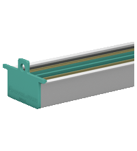
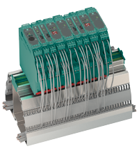
35 mm DIN mounting rail with 3-conductor insert, Provides DC supply voltage to all equipped K-System modules, Standard length 2 m (6 foot), simple to customize to application space, Eliminates daisy-chainspa

35 mm DIN mounting rail with 3-conductor insert, Provides DC supply voltage to all equipped K-System modules, Standard length 0.8 m (2.6 ft), simple to customize to application space, Eliminates daisy-chainspa
Device DTM, For K-, E- and H-System, Frame application, like e. g. PACTware, must be installed separatelypa
Universal DTM host platform, For all DTMs of Pepperl+Fuchs, Approved FDT/DTM technology, Free of charge, Download from Pepperl+Fuchs websitepa
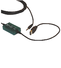
Isolated USB interface cable, Used with K-, E- and H-System devices, Used with PACTwarepa
35 mm DIN mounting rail with 3-conductor insert, Provides DC supply voltage to all equipped K-System modules, Standard length 1.6 m (5 foot), simple to customize to application space, Eliminates daisy-chainspa
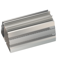
Cable trunking is integrated in the mounting profile, Safe spacious separation of field and control signals, No additional cable guides necessary, Standard length 1.8 m (5.8 ft), simple to customize to application space, With mounting aidspa
Cable trunking with integrated Power Rail UPR-03, Safe spacious separation of field and control signals, No additional cable guides necessary, Provides DC supply voltage to all equipped K-System modules, Standard length 1.8 m (5.8 ft), simple to customize to application space, With end caps UPR-E, cover and mounting aidspa
Universal DTM host platform, For all DTMs of Pepperl+Fuchs, Approved FDT/DTM technology, Free of charge, Download from Pepperl+Fuchs websitepa
Accessories
1-channel, Precision resistor, Conversion of 0 mA ... 20 mA/0 V ... 5 Vpa
1-channel, Precision resistor, Conversion of 4 mA ... 20 mA/2 V ... 10 Vpa
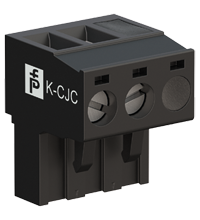
3-pin screw terminal, For KF modules of K-System, Integrated Cold Junction Compensation, Packaging unit: 1 piece, blackpa
3-pin screw terminal, For KF modules of K-System, Packaging unit: 5 pieces greenpa
Coding of K-System terminal blocks, Coding of LB/FB-System front sockets, Packaging unit: 20 x 6 coding pinspa
Safety Products Selector

Choose from various selection criteria like safety integrity level, performance level, device function, and signal type and find the SIL/PL assessed device that you are looking for.