Serviceline Industriële Sensoren
Serviceline Explosiebeveiliging

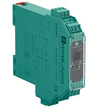
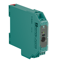
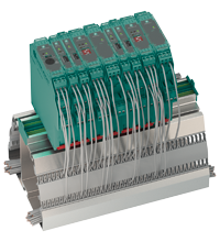
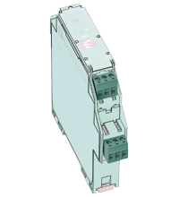
Relay Module KFD2-RSH-1.2D.FL2

KFD2-RSH-1.2D.FL2
  • 1-channel signal conditioner
  • 24 V DC supply
  • Logic input 19 V DC ... 26.4 V DC
  • Recommended connectable voltage 8 V DC ... 60 V DC
  • Relay contact output for de-energized to safe function
  • Line fault transparency (LFT)
  • Diagnostic function
  • Up to SIL 3 acc. to IEC/EN 61508
  • Up to PL e acc. to EN/ISO 13849

Please note: All product-related documents, such as certificates, declarations of conformity, etc., which were issued prior to the conversion under the name Pepperl+Fuchs GmbH or Pepperl+Fuchs AG, also apply to Pepperl+Fuchs SE.

De complete datasheet als PDF downloaden:


Technische gegevens  KFD2-RSH-1.2D.FL2

General specifications
Signal typeDigital Output
Functional safety related parameters
Safety Integrity Level (SIL)SIL 3
Systematic capability (SC)SC 3
Performance level (PL)PL e
Supply
ConnectionPower Rail or terminals 14+, 15-
Rated voltage19 ... 26.4 V DC
Input currentmax. 35 mA at 24 V DC , max. 44 mA at 19 V DC , with enabled internal fault detection
Power consumption< 1.7 W , includes the power consumption of the digital input , see derating curves
Input
Connection sidecontrol side
Connectionterminals 7+, 8-
Pulse/Pause ratiomin. 150 ms / min. 150 ms with disabled internal fault detection
min. 1 s / min. 1 s with enabled internal fault detection
Test pulse lengthmax. 2 ms from DO card
Signal level0-signal: -5 ... 5 V DC
1-signal: 19 ... 26.4 V DC
Rated current0-signal: typ. 1.6 mA at 1.5 V DC; typ. 8 mA at 3 V DC (maximum leakage current DO card)
1-signal: ≥ 36 mA (minimum load current DO card)
Inrush current< 200 mA after 100 µs
Output
Connection sidefield side
Connectionexternal voltage : terminals 4+, 5+, 2-
load : terminals 6, 3
Connectable voltage8 ... 60 V DC
Power dissipation< 3.3 W at 5 A , see derating curves
Contact loading30 V DC / 5 A resistive load , see derating curves
Minimum switch current10 mA
Mechanical life5 x 106 switching cycles
Line fault detectionlow voltage < 5 V DC
undercurrent: 10 mA DC; overcurrent: 2.2 A DC (relay energized)
breakage: 8.2 kΩ; short-circuit: 11 Ω (load, relay de-energized)
Fuse rating2.5 A (scope of delivery)
max. 5 AT, recommended maximum utilization of the fuse: 80 %
Fault indication output
Connectionterminals 10, 11
Contact loading30 V DC/ 0.5 A resistive load
Reaction time< 2 s
Mechanical life105 switching cycles
Transfer characteristics
Switching frequency< 3 Hz with disabled internal fault detection
< 0.5 Hz with enabled internal fault detection
Galvanic isolation
Input/power supplybasic insulation according to IEC/EN 61010-1, rated insulation voltage 60 Veff
Input/fault indication outputbasic insulation according to IEC/EN 61010-1, rated insulation voltage 30 Veff
Output/other circuitsreinforced insulation according to IEC/EN 61010-1, rated insulation voltage 300 Veff
Indicators/settings
Display elementsLEDs
Control elementsDIP switch
Configurationvia DIP switches
Labelingspace for labeling at the front
Directive conformity
Electromagnetic compatibility
Directive 2014/30/EUEN 61326-1:2013 (industrial locations)
Machinery Directive
Directive 2006/42/ECEN 62061:2005+AC:2010+A1:2013+A2:2015 , EN/ISO 13849-1:2015
Conformity
Electromagnetic compatibilityNE 21:2017 , IEC/EN 61326-3-2:2018 , EN 61326-3-1:2017
Degree of protectionIEC 60529:2013
Protection against electrical shockEN 61010-1:2010
Ambient conditions
Ambient temperature-20 ... 60 °C (-4 ... 140 °F)
Observe the temperature range limited by derating, see section derating.
Mechanical specifications
Degree of protectionIP20
Connectionscrew terminals
Massapprox. 142 g
Dimensions20 x 119 x 115 mm (0.8 x 4.7 x 4.5 inch) (W x H x D) , housing type B2
Height119 mm
Width20 mm
Depth115 mm
Mountingon 35 mm DIN mounting rail acc. to EN 60715:2001
General information
Supplementary informationObserve the certificates, declarations of conformity, instruction manuals, and manuals where applicable. For information see www.pepperl-fuchs.com.

Classifications

SystemClasscode
ECLASS 13.027210101
ECLASS 12.027210101
ECLASS 11.027210101
ECLASS 10.0.127210101
ECLASS 9.027210101
ECLASS 8.027210101
ECLASS 5.127210121
ETIM 9.0EC001485
ETIM 8.0EC001485
ETIM 7.0EC001485
ETIM 6.0EC001485
ETIM 5.0EC001485
UNSPSC 12.139121543

Details: KFD2-RSH-1.2D.FL2

Informative Literature: KFD2-RSH-1.2D.FL2

Taalkeuze:
LiteratureTaalBestandstypeBestandsgrootte
Application Report - Biological Cleaning of Wastwater and Secondary Sedimentation StageENGPDF566 KB
Application Report - Generating Electricity in Coal-Fired Power PlantsENGPDF412 KB
Application Report - Sand Trap and Preliminary Sedimentation StageENGPDF448 KB
Application Report - Screening Systems in Sewage Treatment PlantsENGPDF577 KB

Product Documentation: KFD2-RSH-1.2D.FL2

Taalkeuze:
Safety and Security DocumentationTaalBestandstypeBestandsgrootte
HandleidingHOLPDF152 KB
Functional Safety ManualENGPDF1955 KB
Manuals
System ManualENGPDF3694 KB

Design / Simulation: KFD2-RSH-1.2D.FL2

Taalkeuze:
CADTaalBestandstypeBestandsgrootte
CAD 3-D / CAD 3-DALLSTP2510 KB

Approvals: KFD2-RSH-1.2D.FL2

Taalkeuze:
CertificatesCertificaatnummerTaalBestandstypeBestandsgrootte
DNV MarineTAA00001WXALLPDF106 KB
Worldwide TUV Rheinland Functional Safety CertificateTÜV Rheinland Certificate 968/FSP 1538.01/20ALLPDF650 KB
Declaration of Conformity
EU Declaration of Conformity (P+F)TDOC-7537_HOLHOLPDF168 KB

Aanverwante producten: KFD2-RSH-1.2D.FL2

Matching System Components

Interface for Power Rail, Supply current ≤ 4 A, Replaceable fuse, Relay contact output, reversible, LED status indicationpa

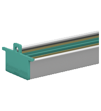
35 mm DIN mounting rail with 3-conductor insert, Provides DC supply voltage to all equipped K-System modules, Standard length 2 m (6 foot), simple to customize to application space, Eliminates daisy-chainspa

35 mm DIN mounting rail with 3-conductor insert, Provides DC supply voltage to all equipped K-System modules, Standard length 0.8 m (2.6 ft), simple to customize to application space, Eliminates daisy-chainspa
35 mm DIN mounting rail with 3-conductor insert, Provides DC supply voltage to all equipped K-System modules, Standard length 1.6 m (5 foot), simple to customize to application space, Eliminates daisy-chainspa
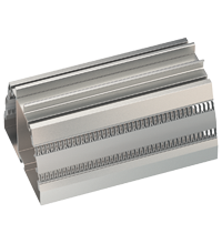
Cable trunking is integrated in the mounting profile, Safe spacious separation of field and control signals, No additional cable guides necessary, Standard length 1.8 m (5.8 ft), simple to customize to application space, With mounting aidspa
Cable trunking with integrated Power Rail UPR-03, Safe spacious separation of field and control signals, No additional cable guides necessary, Provides DC supply voltage to all equipped K-System modules, Standard length 1.8 m (5.8 ft), simple to customize to application space, With end caps UPR-E, cover and mounting aidspa
Accessories
3-pin screw terminal, For KF modules of K-System, Packaging unit: 5 pieces greenpa
Coding of K-System terminal blocks, Coding of LB/FB-System front sockets, Packaging unit: 20 x 6 coding pinspa
Safety Products Selector

Choose from various selection criteria like safety integrity level, performance level, device function, and signal type and find the SIL/PL assessed device that you are looking for.

Veiligheidsrelais van het K-systeem

Pepperl+Fuchs stelt een nieuwe norm qua betrouwbaarheid met haar recent ontwikkelde veiligheidsrelais. Met meervoudig redundante schakelcontacten levert de interfacemodule van het beproefde K-systeem een betrouwbare en veiligheidsrelevante activering en deactivering voor toepassingen in overeenstemming met IEC61508 tot SIL 3-normen.