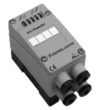
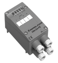
AS-Interface repeater VAR-G4F
- Minimum delay of signal
- Line lengthening by 100 m (max. 2 repeater in series)
- Galvanic isolation between AS-Interface circuits 1 and 2
- No parameterization
- Need no specific address on the AS-Interface bus
- Base for flat cable included in delivery
Please note: All product-related documents, such as certificates, declarations of conformity, etc., which were issued prior to the conversion under the name Pepperl+Fuchs GmbH or Pepperl+Fuchs AG, also apply to Pepperl+Fuchs SE.
Download the complete datasheet as a PDF:
Datasheet excerpt: Technical data of VAR-G4F
| Product Description |
|---|
| AS-Interface Advanced Repeater |
| General specifications | ||
|---|---|---|
| UL File Number | E223772 | |
| Functional safety related parameters | ||
| MTTFd | 160 a at 30 °C | |
| Indicators/operating means | ||
| LED FLT | error display; LED red red: communication error |
|
| LED PWR | AS-Interface voltage; LED green | |
| Electrical specifications | ||
| Rated operating voltage | 26.5 ... 31.6 V from AS-Interface | |
| Rated operating current | 60 mA (per strand element), 120 mA (total) | |
| Directive conformity | ||
| Electromagnetic compatibility | ||
| Directive 2014/30/EU | EN 62026-2:2013 EN 61000-6-2:2005 EN 61000-6-4:2001 | |
| Standard conformity | ||
| Degree of protection | EN 60529:2000 | |
| AS-Interface | EN 62026-2:2013 | |
| Ambient conditions | ||
| Ambient temperature | -10 ... 55 °C (14 ... 131 °F) | |
| Storage temperature | -25 ... 75 °C (-13 ... 167 °F) | |
| Mechanical specifications | ||
| Degree of protection | IP67 | |
| Connection | cable piercing method flat cable yellow |
|
| Material | ||
| Housing | PA 6 GF30 | |
| Mounting | screw mounting | |
Classifications
| System | Classcode |
|---|---|
| ECLASS 13.0 | 27040301 |
| ECLASS 12.0 | 27040301 |
| ECLASS 11.0 | 27040301 |
| ECLASS 10.0.1 | 27040301 |
| ECLASS 9.0 | 27040301 |
| ECLASS 8.0 | 27040301 |
| ECLASS 5.1 | 27040301 |
| ETIM 9.0 | EC001449 |
| ETIM 8.0 | EC001449 |
| ETIM 7.0 | EC001449 |
| ETIM 6.0 | EC001449 |
| ETIM 5.0 | EC002540 |
| UNSPSC 12.1 | 39121535 |
Details: VAR-G4F
Function
The Advanced-Repeater VAR-G4F isolates two AS-Interface circuits galvanically from each other and processes the AS-Interface signals electrically, which extends the maximum line length by 100 m. Two Advanced-Repeaters can be connected in series resulting in a maximum line length of 300 m.
The Advanced-Repeater features an alignment between sender and receiver that has been optimized even further and offers a shorter delay when the signals pass through the Advanced-Repeater.
The Advanced-Repeater does not need any parameterization nor its own address on the AS-Interface; the total number of slaves (31 or 62) per line remains as it is.
A flat or round cable can be used for the connection to the AS-Interface transmission line. If the AS-Interface flat cable is to be used, the bottom part included in the scope of delivery is required. The contact to the two AS-Interface lines is made via the standardized EMS interface, i.e. by using the insulation penetration technique.
Due to the galvanic isolation, a power supply or power extender is required for each segment.
Two LEDs indicate the correct polarity of the AS-Interface lines, two LEDs signal communication faults in the respective AS-Interface circuits.
Design / Simulation: VAR-G4F
| CAD | Language | File Type | File Size |
|---|---|---|---|
| CAD 3-D / CAD 3-D | ALL | STP | 2960 KB |
| CAD Portal / CAD Portal | ALL | LINK | --- |
Approvals: VAR-G4F
| Certificates | Cert No. | Language | File Type | File Size |
|---|---|---|---|---|
| US CA UL | E223772 | ALL | LINK | --- |
| Declaration of Conformity | ||||
| EU Declaration of Conformity (P+F) / EU-Konformitäterklärung (P+F) | DOC-2454C | ALL | 109 KB | |
Associated Products: VAR-G4F
| Accessory of | ||||||
|---|---|---|---|---|---|---|
|
||||||
| Accessories | ||||||
|
||||||


 +65 6779 9091