

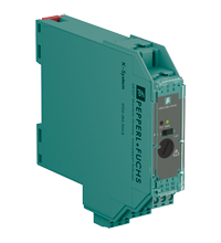
Redundant Power Feed Module KFD2-EB2.R4A.B
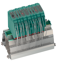
- Interface for Power Rail
- Used for redundant configuration
- Supply current ≤ 4 A
- Replaceable fuse
- Relay contact output, reversible
- LED status indication


Please note: All product-related documents, such as certificates, declarations of conformity, etc., which were issued prior to the conversion under the name Pepperl+Fuchs GmbH or Pepperl+Fuchs AG, also apply to Pepperl+Fuchs SE.
Datasheet excerpt: Technical data of KFD2-EB2.R4A.B
| Product Description |
|---|
| Power feed module, redundant supply |
| Supply | ||
|---|---|---|
| Connection | terminals 11+, 12- terminals 8+, 9- |
|
| Rated voltage | 20 ... 30 V DC The maximum rated operating voltage of the devices plugged onto the Power Rail must not be exceeded. |
|
| Fusing | 5 AT/250 V AC recommended maximum utilization of the fuse: 80 % |
|
| Power dissipation | ≤ 2.4 W | |
| Output | ||
| Connection | Power Rail | |
| Output current | max. 4 A | |
| Output voltage | Ui ≥ rated voltage Ur = Ui - 0.6 V | |
| Fault signal | relay output: NO contact | |
| Contact loading | 30 V AC/ 2 A / cos φ ≥ 0.7 ; 40 V DC/ 2 A | |
| Energized/De-energized delay | approx. 20 ms / approx. 20 ms | |
| Indicators/settings | ||
| Display elements | LEDs | |
| Control elements | DIP switch | |
| Configuration | via DIP switches | |
| Labeling | space for labeling at the front | |
| Directive conformity | ||
| Electromagnetic compatibility | ||
| Directive 2014/30/EU | EN 61326-1:2013 (industrial locations) | |
| Conformity | ||
| Electromagnetic compatibility | NE 21:2006 | |
| Degree of protection | IEC 60529:2001 | |
| Ambient conditions | ||
| Ambient temperature | -40 ... 60 °C (-40 ... 140 °F) extended ambient temperature range up to 70 °C (158 °F), refer to manual for necessary mounting conditions |
|
| Mechanical specifications | ||
| Degree of protection | IP20 | |
| Connection | screw terminals | |
| Mass | approx. 100 g | |
| Dimensions | 20 x 119 x 115 mm (0.8 x 4.7 x 4.5 inch) (W x H x D) , housing type B2 | |
| Height | 119 mm | |
| Width | 20 mm | |
| Depth | 115 mm | |
| Mounting | on 35 mm DIN mounting rail acc. to EN 60715:2001 | |
| Data for application in connection with hazardous areas | ||
| Certificate | UL 22 ATEX 2853 X | |
| Marking |  II 3G Ex ec nC IIC T4 Gc II 3G Ex ec nC IIC T4 Gc |
|
| Directive conformity | ||
| Directive 2014/34/EU | EN IEC 60079-0:2018+AC:2020 , EN IEC 60079-7:2015+A1:2018 , EN IEC 60079-15:2019 | |
| International approvals | ||
| FM approval | FM 22 US 0031 X | |
| Control drawing | 116-0160 | |
| UL approval | E106378 | |
| CSA approval | CoC 1051840 | |
| IECEx approval | ||
| IECEx certificate | IECEx UL 16.0051X | |
| IECEx marking | Ex ec nC IIC T4 Gc | |
| General information | ||
| Supplementary information | Observe the certificates, declarations of conformity, instruction manuals, and manuals where applicable. For information see www.pepperl-fuchs.com. | |
Classifications
| System | Classcode |
|---|---|
| ECLASS 13.0 | 27210119 |
| ECLASS 12.0 | 27210119 |
| ECLASS 11.0 | 27210119 |
| ECLASS 10.0.1 | 27210119 |
| ECLASS 9.0 | 27210119 |
| ECLASS 8.0 | 27210119 |
| ECLASS 5.1 | 27210119 |
| ETIM 9.0 | EC002653 |
| ETIM 8.0 | EC002653 |
| ETIM 7.0 | EC002653 |
| ETIM 6.0 | EC002653 |
| ETIM 5.0 | EC002542 |
| UNSPSC 12.1 | 39121004 |
Details: KFD2-EB2.R4A.B
The power feed module supplies the Power Rail with a voltage of 24 V DC and a maximum current of 4 A. The device is designed for applications requiring redundant power.
In the event of a device fault or a wiring fault of any isolator on the Power Rail, the collective error messaging relay alerts the controller via a binary I/O point. This relay can be configured as normally-open or normally-closed.
A green LED on the front of the device indicates the power state, and a red LED lights up during a fault condition.
Additionally, the bus implemented in the Power Rail is forwarded to the terminals 13 and 15 for usage with the RS-485 connection of the KFD2-WAC2-Ex1.D device. Terminal 14 is only for test purposes.
In the sense of functional safety (SIL) the device provides no dangerous failures. Thereby the safe condition of the supplied isolators must be defined as the de-energized state. Thus the device will not influence the safety calculation or the SIL value.
This device is compatible with all versions of the Power Rail and provides group fusing.
Note: Redundant systems require 2 KFD2-EB.R4A.B power feed modules.
Datasheet: KFD2-EB2.R4A.B
| Datasheet | File Type | File Size |
|---|---|---|
| Datasheet KFD2-EB2.R4A.B | 1075 KB | |
| Fiche de données KFD2-EB2.R4A.B | 1079 KB | |
| Datenblatt KFD2-EB2.R4A.B | 1077 KB | |
| Datasheet KFD2-EB2.R4A.B | 1082 KB | |
| Hoja de datos KFD2-EB2.R4A.B | 1077 KB |
Documents: KFD2-EB2.R4A.B
CAD+CAE: KFD2-EB2.R4A.B
| CAD | File Type | File Size |
|---|---|---|
| CAD 3-D / CAD 3-D | STP | 2510 KB |
| CAD Portal / CAD Portal | LINK | --- |
| EPLAN | ||
| EPLAN macro EDZ / EPLAN Makro EDZ | EDZ | 59 KB |
Approvals+Certificates: KFD2-EB2.R4A.B
Associated Products: KFD2-EB2.R4A.B
| Accessory of | ||||||
|---|---|---|---|---|---|---|
|
||||||
|
||||||
|
||||||
|
||||||
| Matching System Components | ||||||
|
||||||
|
||||||
|
||||||
|
||||||
|
||||||
| Accessories | ||||||
|
||||||
|
||||||


Choose from various selection criteria like safety integrity level, performance level, device function, and signal type and find the SIL/PL assessed device that you are looking for.


Pepperl+Fuchs SE
Lilienthalstraße 200
68307 Mannheim
Germany
info@de.pepperl-fuchs.com
 +49 621 776-0
Pepperl+Fuchs is a leading developer and manufacturer of electronic sensors and components for the global automation market. Continuous innovation, enduring quality, and steady growth have been the foundation of our success for more than 70 years. Pepperl+Fuchs employs 6,300 people worldwide and has manufacturing facilities in Germany, USA, Singapore, Hungary, Indonesia and Vietnam, most of them ISO 9001 certified.