

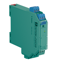
SMART Transmitter Power Supply KFD2-STC5-Ex2
- 2-channel isolated barrier
- 24 V DC supply (Power Rail)
- Input 2-wire and 3-wire SMART transmitters and 2-wire SMART current sources
- Output 4 mA ... 20 mA current sink/current source
- Terminals with test points
- Up to SIL 2 (SC 3) acc. to IEC/EN 61508


Please note: All product-related documents, such as certificates, declarations of conformity, etc., which were issued prior to the conversion under the name Pepperl+Fuchs GmbH or Pepperl+Fuchs AG, also apply to Pepperl+Fuchs SE.
Datasheet excerpt: Technical data of KFD2-STC5-Ex2
| General specifications | ||
|---|---|---|
| Signal type | Analog input | |
| Functional safety related parameters | ||
| Safety Integrity Level (SIL) | SIL 2 | |
| Systematic capability (SC) | SC 3 | |
| Supply | ||
| Connection | Power Rail or terminals 14+, 15- | |
| Rated voltage | 18 ... 30 V DC | |
| Ripple | within the supply tolerance | |
| Power dissipation | ≤ 1.4 W at maximum load | |
| Power consumption | ≤ 2.6 W at maximum load | |
| Input | ||
| Connection side | field side | |
| Connection | terminals 1+, 2-, 3; 4+, 5-, 6 | |
| Input signal | 4 ... 20 mA | |
| Open circuit voltage/short-circuit current | terminals 1+, 3; 4+, 6: 23 V / 25 mA | |
| Input resistance | max. 265 Ω terminals 2-, 3; 5-, 6 , max. 330 Ω terminals 1+, 3; 4+, 6 | |
| Available voltage | ≥ 16 V at 20 mA ; ≥ 20 V at 4 mA , terminals 1+, 3; 4+, 6 | |
| Output | ||
| Connection side | control side | |
| Connection | terminals 7+, 8-, 9-; 10+, 11-, 12- (sink) terminals 7-, 8+, 9+; 10-, 11+, 12+ (source) see additional information |
|
| Load | 0 ... 600 Ω | |
| Output signal | 4 ... 20 mA (overload > 25 mA) | |
| Ripple | max. 50 µA rms | |
| External supply (loop) | 2 ... 30 V DC If the external voltage is > 19 V, a load ≥ ((V - 19) / 0.02) Ω is required. V represents the value of the external voltage. The internal 250 Ω resistor at terminals 9 and 12 can be used as a load. |
|
| Transfer characteristics | ||
| Deviation | at 20 °C (68 °F), 4 ... 20 mA ≤ 10 µA incl. calibration, linearity, hysteresis, loads and fluctuations of supply voltage |
|
| Influence of ambient temperature | ≤ 0.25 µA/K | |
| Frequency range | field side into the control side: band width with 1 Vpp signal 0 ... 7.5 kHz (-3 dB) safe area to hazardous area: band width with 1 VSS signal 0.3 ... 7.5 kHz (-3 dB) |
|
| Settling time | 200 µs | |
| Rise time/fall time | 100 µs | |
| Galvanic isolation | ||
| Output/power supply | functional insulation, rated insulation voltage 50 V AC | |
| Output/Output | functional insulation, rated insulation voltage 50 V AC | |
| Indicators/settings | ||
| Display elements | LED | |
| Labeling | space for labeling at the front | |
| Directive conformity | ||
| Electromagnetic compatibility | ||
| Directive 2014/30/EU | EN 61326-1:2013 (industrial locations) | |
| Conformity | ||
| Electromagnetic compatibility | NE 21:2012 EN 61326-3-2:2008 |
|
| Degree of protection | IEC 60529:2001 | |
| Protection against electrical shock | UL 61010-1:2012 | |
| Ambient conditions | ||
| Ambient temperature | -20 ... 60 °C (-4 ... 140 °F) extended ambient temperature range up to 70 °C (158 °F), refer to manual for necessary mounting conditions |
|
| Mechanical specifications | ||
| Degree of protection | IP20 | |
| Connection | screw terminals | |
| Mass | approx. 200 g | |
| Dimensions | 20 x 124 x 115 mm (0.8 x 4.9 x 4.5 inch) (W x H x D) , housing type B2 | |
| Height | 124 mm | |
| Width | 20 mm | |
| Depth | 115 mm | |
| Mounting | on 35 mm DIN mounting rail acc. to EN 60715:2001 | |
| Data for application in connection with hazardous areas | ||
| EU-type examination certificate | CML 17 ATEX 2031X | |
| Marking |  II (1)G [Ex ia Ga] IIC II (1)D [Ex ia Da] IIIC I (M1) [Ex ia Ma] I II (1)G [Ex ia Ga] IIC II (1)D [Ex ia Da] IIIC I (M1) [Ex ia Ma] I |
|
| Input | [Ex ia Ga] IIC, [Ex ia Da] IIIC, [Ex ia Ma] I | |
| Supply | ||
| Maximum safe voltage | 250 V (Attention! The rated voltage can be lower.) | |
| Equipment | terminals 1+, 3-; 4+, 6- | |
| Voltage | 26.2 V | |
| Voltage | 27.25 V | |
| Current | 93 mA | |
| Power | 634 mW | |
| Equipment | terminals 2-, 3+; 5-, 6+ | |
| Voltage | 30 V | |
| Current | 115 mA | |
| Power | max 1 W | |
| Voltage | 2 V | |
| Current | 8.5 mA | |
| Power | 4.3 mW | |
| Equipment | terminals 1+, 2/3-; 4+, 5/6- | |
| Voltage | 26.2 V | |
| Voltage | 27.25 V | |
| Current | 115 mA | |
| Power | 784 mW | |
| Certificate | CML 17 ATEX 3030X | |
| Marking | II 3G Ex ec IIC T4 Gc |
|
| Galvanic isolation | ||
| Input/Output | safe electrical isolation acc. to IEC/EN 60079-11:2007, voltage peak value 375 V | |
| Input/power supply | safe electrical isolation acc. to IEC/EN 60079-11:2007, voltage peak value 375 V | |
| Directive conformity | ||
| Directive 2014/34/EU | EN IEC 60079-0:2018+AC:2020 , EN 60079-7:2015+A1:2018 , EN 60079-11:2012 | |
| International approvals | ||
| UL approval | E106378 | |
| Control drawing | 116-0439 (cULus) | |
| IECEx approval | ||
| IECEx certificate | IECEx CML 17.0016X | |
| IECEx marking | [Ex ia Ga] IIC , [Ex ia Da] IIIC , [Ex ia Ma] I Ex ec IIC T4 Gc |
|
| General information | ||
| Supplementary information | Observe the certificates, declarations of conformity, instruction manuals, and manuals where applicable. For information see www.pepperl-fuchs.com. | |
Classifications
| System | Classcode |
|---|---|
| ECLASS 13.0 | 27210119 |
| ECLASS 12.0 | 27210119 |
| ECLASS 11.0 | 27210119 |
| ECLASS 10.0.1 | 27210119 |
| ECLASS 9.0 | 27210119 |
| ECLASS 8.0 | 27210119 |
| ECLASS 5.1 | 27210119 |
| ETIM 9.0 | EC001485 |
| ETIM 8.0 | EC001485 |
| ETIM 7.0 | EC001485 |
| ETIM 6.0 | EC001485 |
| ETIM 5.0 | EC001485 |
| UNSPSC 12.1 | 32101514 |
Details: KFD2-STC5-Ex2
This isolated barrier is used for intrinsic safety applications.
The device supplies 2-wire and 3-wire SMART transmitters, and can also be used with 2-wire SMART current sources.
It transfers the analog input signal to the safe area as an isolated current value.
Digital signals may be superimposed on the input signal in the hazardous or non-hazardous area and are transferred bi-directionally.
The device provides a sink mode or a source mode output on the safe area terminals.
The device has an internal resistor. Use this resistor if the HART communication resistance in the control circuit is too low.
Test sockets for the connection of HART communicators are integrated into the terminals of the device.
Datasheet: KFD2-STC5-Ex2
| Datasheet | File Type | File Size |
|---|---|---|
| Datasheet KFD2-STC5-Ex2 | 1119 KB | |
| Fiche de données KFD2-STC5-Ex2 | 1130 KB | |
| Datenblatt KFD2-STC5-Ex2 | 1122 KB | |
| Datasheet KFD2-STC5-Ex2 | 1176 KB | |
| Hoja de datos KFD2-STC5-Ex2 | 1132 KB |
Documents: KFD2-STC5-Ex2
CAD+CAE: KFD2-STC5-Ex2
| CAD | File Type | File Size |
|---|---|---|
| CAD 3-D / CAD 3-D | STP | 3048 KB |
| CAD Portal / CAD Portal | LINK | --- |
| EPLAN | ||
| CAE EPLAN Data Portal / CAE EPLAN Data Portal | LINK | --- |
| CAE EPLAN macro EDZ / CAE EPLAN Makro EDZ | EDZ | 1646 KB |
Approvals+Certificates: KFD2-STC5-Ex2
Associated Products: KFD2-STC5-Ex2
| Matching System Components | ||||||
|---|---|---|---|---|---|---|
|
||||||
|
||||||
|
||||||
|
||||||
|
||||||
|
||||||
| Accessories | ||||||
|
||||||
|
||||||
|
||||||
|
||||||
|
||||||
|
||||||


Choose from various selection criteria like safety integrity level, performance level, device function, and signal type and find the SIL/PL assessed device that you are looking for.


Pepperl+Fuchs SE
Lilienthalstraße 200
68307 Mannheim
Germany
info@de.pepperl-fuchs.com
 +49 621 776-0
Pepperl+Fuchs is a leading developer and manufacturer of electronic sensors and components for the global automation market. Continuous innovation, enduring quality, and steady growth have been the foundation of our success for more than 70 years. Pepperl+Fuchs employs 6,300 people worldwide and has manufacturing facilities in Germany, USA, Singapore, Hungary, Indonesia and Vietnam, most of them ISO 9001 certified.