| General specifications |
| Signal type | Analog input |
| Supply |
| Rated voltage | 12 ... 35 V DC loop powered |
| Power dissipation | 0.4 W |
| Input |
| Connection side | field side |
| Connection | terminals 1+, 2-, 3- thermocouple E, J, K, N, R, S or T, cold junction referenced to 0 °C (32 °F) |
| Lead resistance | max. 100 Ω per line |
| Current | lead monitoring ON: ≤ 15 nA; OFF: ≤ 1 nA |
| Output |
| Connection side | control side |
| Connection | terminals 9+, 8- |
| Load | (U -12 V) / 0.02 A |
| Current output | 4 ... 20 mA , limited to ≤ 35 mA |
| Fault signal | downscaling ≤ 3 mA , upscaling ≥ 22 mA |
| Transfer characteristics |
| Measuring range | span 4 ... 100 mV, zero point -12 ... 60 mV , both adjustable |
| Deviation | |
| After calibration | 0.1 % of full-scale value ± 1 K for the cold junction |
| Temperature effect | temperature deviation 0.015 % of the span/K or 1.5 µV/K cold junction ± 2 K (calibrated at Tamb = 20 °C (68 °F)) |
| Influence of supply voltage | 6.5 ppm/V |
| Characteristic curve | the output voltage is linearly proportionate to the input voltage (not to temperature) |
| Rise time | 250 ms |
| Galvanic isolation |
| Input/Output | safe isolation according to EN 50178, rated insulation voltage 253 Veff |
| Indicators/settings |
| Control elements | DIP switch
rotary switch |
| Configuration | via DIP switches
via rotary switch |
| Labeling | space for labeling at the front |
| Directive conformity |
| Electromagnetic compatibility | |
| Directive 2014/30/EU | EN 61326-1:2013 (industrial locations) |
| Conformity |
| Insulation coordination | EN 50178 |
| Galvanic isolation | EN 50178 |
| Degree of protection | IEC 60529 |
| Ambient conditions |
| Ambient temperature | -20 ... 60 °C (-4 ... 140 °F) |
| Mechanical specifications |
| Degree of protection | IP20 |
| Connection | screw terminals |
| Mass | approx. 150 g |
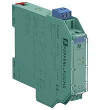
| Dimensions | 20 x 119 x 115 mm (0.8 x 4.7 x 4.5 inch) (W x H x D) , housing type B2 |
| Height | 119 mm |
| Width | 20 mm |
| Depth | 115 mm |
| Mounting | on 35 mm DIN mounting rail acc. to EN 60715:2001 |
| Data for application in connection with hazardous areas |
| EU-type examination certificate | ZELM 00 ATEX 0035 |
| Marking |  II (1)GD [EEx ia] IIC II (1)GD [EEx ia] IIC |
| Voltage | 16.1 V |
| Current | 0.8 mA |
| Power | 3.2 mW |
| Output | |
| Maximum safe voltage | 60 V (Attention! The rated voltage can be lower.) |
| Certificate | TÜV 01 ATEX 1777 X |
| Marking |  II 3G Ex nA II T4 II 3G Ex nA II T4 |
| Galvanic isolation | |
| Input/Output | safe electrical isolation acc. to IEC/EN 60079-11, voltage peak value 375 V |
| Directive conformity | |
| Directive 2014/34/EU | EN 60079-0:2012+A11:2013 , EN 60079-11:2012 , EN 60079-15:2010 |
| International approvals |
| CSA approval | |
| Control drawing | 116-0132 |
| General information |
| Supplementary information | Observe the certificates, declarations of conformity, instruction manuals, and manuals where applicable. For information see www.pepperl-fuchs.com. |
 II (1)GD [EEx ia] IIC
 II 3G Ex nA II T4




 +45 7010 4210