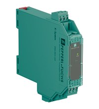
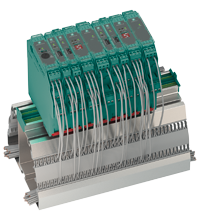
SMART Transmitter Power Supply KFD2-STC5-1.2O
- 1-channel signal conditioner
- 24 V DC supply (Power Rail)
- Input 2-wire and 3-wire SMART transmitters and 2-wire SMART current sources
- Signal splitter (1 input and 2 outputs)
- Dual output 4 mA ... 20 mA current sink/current source
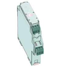
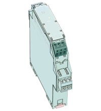
- Terminals with test points
- Up to SIL 2 (SC 3) acc. to IEC/EN 61508
Please note: All product-related documents, such as certificates, declarations of conformity, etc., which were issued prior to the conversion under the name Pepperl+Fuchs GmbH or Pepperl+Fuchs AG, also apply to Pepperl+Fuchs SE.
Hent hele databladet som PDF:
Uddrag af datablad: Tekniske data for KFD2-STC5-1.2O
| General specifications | ||
|---|---|---|
| Signal type | Analog input | |
| Functional safety related parameters | ||
| Safety Integrity Level (SIL) | SIL 2 | |
| Systematic capability (SC) | SC 3 | |
| Supply | ||
| Connection | Power Rail or terminals 14+, 15- | |
| Rated voltage | 18 ... 30 V DC | |
| Ripple | within the supply tolerance | |
| Power dissipation | ≤ 1 W at maximum load | |
| Power consumption | ≤ 1.7 W at maximum load | |
| Input | ||
| Connection side | field side | |
| Connection | terminals 1+, 2-, 3 | |
| Input signal | 4 ... 20 mA | |
| Open circuit voltage/short-circuit current | terminals 1+, 3: 23 V / 25 mA | |
| Input resistance | max. 265 Ω terminals 2-, 3 , max. 330 Ω terminals 1+, 3 | |
| Available voltage | ≥ 16 V at 20 mA ; ≥ 20 V at 4 mA , terminals 1+, 3 | |
| Output | ||
| Connection side | control side | |
| Connection | terminals 7+, 8-, 9-; 10+, 11-, 12- (sink) terminals 7-, 8+, 9+; 10-, 11+, 12+ (source) see additional information |
|
| Load | 0 ... 600 Ω | |
| Output signal | 4 ... 20 mA (overload > 25 mA) | |
| Ripple | max. 50 µA eff | |
| External supply (loop) | 2 ... 30 V DC If the external voltage is > 19 V, a load ≥ ((V - 19) / 0.02) Ω is required. V represents the value of the external voltage. The internal 250 Ω resistor at terminals 9 and 12 can be used as a load. |
|
| Transfer characteristics | ||
| Deviation | at 20 °C (68 °F), 4 ... 20 mA ≤ ± 10 µA incl. calibration, linearity, hysteresis, loads and supply voltage fluctuations |
|
| Influence of ambient temperature | ≤ 0.25 µA/K | |
| Frequency range | input in output: bandwidth with 1 mApp signal 0 ... 7.5 kHz (-3 dB) output in input: band width with 1 Vss signal 0.3 ... 7.5 kHz (-3 dB) |
|
| Settling time | 200 µs | |
| Rise time/fall time | 100 µs | |
| Galvanic isolation | ||
| Input/Output | basic insulation according to IEC 61010-1, rated insulation voltage 300 Veff | |
| Input/power supply | basic insulation according to IEC 61010-1, rated insulation voltage 300 Veff | |
| Output/power supply | functional insulation, rated insulation voltage 50 V AC | |
| Output/Output | functional insulation, rated insulation voltage 50 V AC | |
| Indicators/settings | ||
| Display elements | LED | |
| Labeling | space for labeling at the front | |
| Directive conformity | ||
| Electromagnetic compatibility | ||
| Directive 2014/30/EU | EN 61326-1:2013 (industrial locations) | |
| Conformity | ||
| Electromagnetic compatibility | NE 21:2012 EN 61326-3-2:2008 |
|
| Degree of protection | IEC 60529:2001 | |
| Protection against electrical shock | UL 61010-1:2012 | |
| Ambient conditions | ||
| Ambient temperature | -20 ... 70 °C (-4 ... 158 °F) | |
| Mechanical specifications | ||
| Degree of protection | IP20 | |
| Connection | screw terminals | |
| Mass | approx. 150 g | |
| Dimensions | 20 x 124 x 115 mm (0.8 x 4.9 x 4.5 inch) (W x H x D) , housing type B2 | |
| Height | 124 mm | |
| Width | 20 mm | |
| Depth | 115 mm | |
| Mounting | on 35 mm DIN mounting rail acc. to EN 60715:2001 | |
| General information | ||
| Supplementary information | Observe the certificates, declarations of conformity, instruction manuals, and manuals where applicable. For information see www.pepperl-fuchs.com. | |
Classifications
| System | Classcode |
|---|---|
| ECLASS 13.0 | 27210119 |
| ECLASS 12.0 | 27210119 |
| ECLASS 11.0 | 27210119 |
| ECLASS 10.0.1 | 27210119 |
| ECLASS 9.0 | 27210119 |
| ECLASS 8.0 | 27210119 |
| ECLASS 5.1 | 27210119 |
| ETIM 9.0 | EC001485 |
| ETIM 8.0 | EC001485 |
| ETIM 7.0 | EC001485 |
| ETIM 6.0 | EC001485 |
| ETIM 5.0 | EC001485 |
| UNSPSC 12.1 | 32101514 |
Details: KFD2-STC5-1.2O
Informative Literature: KFD2-STC5-1.2O
| Literature | Sprog | Fil type | Fil størrelse |
|---|---|---|---|
| Application Report - Generating Electricity in Coal-Fired Power Plants | ENG | 412 KB | |
| Application Report - Screening Systems in Sewage Treatment Plants | ENG | 577 KB |
Product Documentation: KFD2-STC5-1.2O
| Safety and Security Documentation | Sprog | Fil type | Fil størrelse |
|---|---|---|---|
| Instruktions manual | DAN | 47 KB | |
| Functional Safety Manual | ENG | 1946 KB | |
| Functional Safety Manual | ENG | 1974 KB | |
| Manuals | |||
| System Manual | ENG | 3694 KB | |
Design / Simulation: KFD2-STC5-1.2O
| CAD | Sprog | Fil type | Fil størrelse |
|---|---|---|---|
| CAD 3-D / CAD 3-D | ALL | STP | 3048 KB |
| CAD Portal / CAD Portal | ALL | LINK | --- |
| CAE | |||
| CAE EPLAN Data Portal / CAE EPLAN Data Portal | ALL | LINK | --- |
| CAE EPLAN macro EDZ / CAE EPLAN Makro EDZ | ALL | EDZ | 1637 KB |
Approvals: KFD2-STC5-1.2O
| Certificates | Certifikat nr. | Sprog | Fil type | Fil størrelse |
|---|---|---|---|---|
| USA Canada UL Hazardous Location Certificate of Compliance cULus UL E106378 | CoC E106378 RepRef E106378-20171103 | ALL | 413 KB | |
| Worldwide TUV Rheinland | 968/FSP 1498.01/24 | ALL | 617 KB | |
| Declaration of Conformity | ||||
| EU Declaration of Conformity (P+F) / EU-Konformitäterklärung (P+F) | DOC-3647A | ALL | 100 KB | |
| UKCA-Declaration of conformity / UKCA-Konformitätserklärung | DOC-5298 | ALL | 63 KB | |
Tilhørende produkter: KFD2-STC5-1.2O
| Matching System Components | ||||||
|---|---|---|---|---|---|---|
|
||||||
|
||||||
|
||||||
|
||||||
|
||||||
|
||||||
| Accessories | ||||||
|
||||||
|
||||||
|
||||||

With the publication of Regulation (EU) 2023/1230 of the European Parliament and of the Council on machinery, the previously applicable European Machinery Directive 2006/42/EC has recently been replaced. As things stand today, we assume that Pepperl+Fuchs products that fall within the scope of the EU Machinery Regulation will also comply with it. Please read the full statement for more information.




 +45 7010 4210