

Not available for purchase
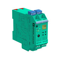
Temperature Converter with Trip Values KFD2-GUT-Ex1.D
- 1-channel isolated barrier
- 24 V DC supply (Power Rail)
- Thermocouple, RTD, potentiometer or voltage input
- Redundant TC input
- Current output 0/4 mA ... 20 mA
- 2 relay contact outputs
- Configurable by PACTware or keypad
- Line fault (LFD) and sensor burnout detection
- Up to SIL 2 acc. to IEC 61508


Please note: All product-related documents, such as certificates, declarations of conformity, etc., which were issued prior to the conversion under the name Pepperl+Fuchs GmbH or Pepperl+Fuchs AG, also apply to Pepperl+Fuchs SE.
Download the complete datasheet as a PDF:
Datasheet excerpt: Technical data of KFD2-GUT-Ex1.D
| General specifications | ||
|---|---|---|
| Signal type | Analog input | |
| Supply | ||
| Connection | terminals 23+, 24- or power feed module/Power Rail | |
| Rated voltage | 20 ... 30 V DC | |
| Rated current | approx. 100 mA | |
| Power dissipation/power consumption | ≤ 2 W / 2.2 W | |
| Input | ||
| Connection | terminals 1, 2, 3, 4, 6 |
|
| RTD | Pt100, Pt500, Pt1000, Ni100, Ni1000 | |
| Types of measuring | 2-, 3-, 4-wire technology | |
| Lead resistance | max. 50 Ω | |
| Measurement loop monitoring | sensor breakage, sensor short-circuit | |
| Thermocouples | type B, E, J, K, L, N, R, S, T (IEC 584-1: 1995) | |
| Cold junction compensation | external and internal | |
| Measurement loop monitoring | sensor breakage | |
| Potentiometer | 0.8 ... 20 kΩ | |
| Types of measuring | 2-, 3-, 5-wire technology | |
| Voltage | 0 ... 10 V , 2 ... 10 V , 0 ... 1 V , -100 ... 100 mV | |
| Input resistance | ≥ 250 kΩ (0 ... 10 V) min. 1 MΩ (0 ... 1 V, -100 ... 100 mV) |
|
| Measuring current | approx. 400 µA with resistance measuring sensor | |
| Output | ||
| Connection | output I: terminals 10, 11, 12 output II: terminals 16, 17, 18 output III: terminals 8+, 7- |
|
| Output I, II | relay | |
| Contact loading | 250 V AC / 2 A / cos φ ≥ 0.7 ; 40 DC / 2 A | |
| Mechanical life | 5 x 10⁷ switching cycles | |
| Energized/De-energized delay | approx. 20 ms / approx. 20 ms | |
| Output III | Analog current output | |
| Current range | 0 ... 20 mA or 4 ... 20 mA | |
| Open loop voltage | max. 24 V DC | |
| Load | max. 650 Ω | |
| Fault signal | downscale I ≤ 3.6 mA, upscale I ≥ 21 mA (acc. NAMUR NE43) | |
| Transfer characteristics | ||
| Deviation | ||
| Temperature effect | Input: 0.005 %/K (50 ppm) of span ; current output: 0.005 %/K (50 ppm) of span | |
| RTD | max. 0.2 % of span | |
| Thermocouples | max. 10µV deviation of CJC: ±0.8 K |
|
| Voltage | 0.1 % of span | |
| Potentiometer | 0.1 % of span when < 5 kΩ 0.5 % of span when > 5 kΩ |
|
| Current output | max. 20 µA | |
| Sampling rate | approx. 700 ms | |
| Galvanic isolation | ||
| Input/Other circuits | safe galvanic isolation acc. to EN 50020, voltage peak value 375 V | |
| Output I, II against eachother | reinforced insulation according to IEC 61140, rated insulation voltage 300 Veff | |
| Output I, II/other circuits | reinforced insulation according to IEC 61140, rated insulation voltage 300 Veff | |
| Output III/power supply and collective error | reinforced insulation according to IEC 61140, rated insulation voltage 300 Veff | |
| Interface/power supply | reinforced insulation according to IEC 61140, rated insulation voltage 300 Veff | |
| Directive conformity | ||
| Electromagnetic compatibility | ||
| Directive 2004/108/EC | EN 61326-1:2006 | |
| Low voltage | ||
| Directive 2006/95/EC | EN 50178:1997 | |
| Conformity | ||
| Insulation coordination | EN 50178 | |
| Galvanic isolation | EN 50178 | |
| Electromagnetic compatibility | NE 21 | |
| Degree of protection | IEC 60529 | |
| Ambient conditions | ||
| Ambient temperature | -20 ... 60 °C (-4 ... 140 °F) | |
| Mechanical specifications | ||
| Degree of protection | IP20 | |
| Mass | 300 g | |
| Dimensions | 40 x 119 x 115 mm (1.6 x 4.7 x 4.5 inch) , housing type C2 | |
| Height | 119 mm | |
| Width | 40 mm | |
| Length | 115 mm | |
| Mounting | on 35 mm DIN mounting rail acc. to EN 60715:2001 | |
| Data for application in connection with hazardous areas | ||
| EU-type examination certificate | TÜV 03 ATEX 2140 , for additional certificates see www.pepperl-fuchs.com | |
| Marking |  II (1) G [Ex ia] IIC II (1) D [Ex iaD] II (1) G [Ex ia] IIC II (1) D [Ex iaD] |
|
| Input | Ex ia IIC, Ex iaD | |
| Supply | ||
| Maximum safe voltage | 40 V DC (Attention! The rated voltage can be lower.) | |
| Input | terminals 2, 6 (for active equipment) | |
| Voltage | 13.1 V | |
| Current | 8 mA | |
| Power | 67 mW | |
| Voltage | 29 V | |
| Current | 11 mA | |
| Power | 200 mW | |
| Inputs | terminals 1, 2, 3, 4, 6 (for passive equipment) | |
| Voltage | 13.1 V | |
| Current | 21 mA | |
| Power | 67 mW | |
| Output | ||
| Contact loading | 253 V AC/2 A/cos φ > 0.7; 40 V DC/2 A resistive load (TÜV 03 ATEX 2140) |
|
| Analog output | ||
| Maximum safe voltage | 40 V (Attention! The rated voltage can be lower.) | |
| Interface | ||
| Maximum safe voltage | 40 V (Attention! The rated voltage can be lower.) , RS 232 | |
| Certificate | Pepperl+Fuchs | |
| Marking | II 3G Ex nA nC IIC T4 X |
|
| Output I, II | ||
| Contact loading | 50 V AC/2 A/cos φ > 0.7; 40 V DC/1 A resistive load | |
| Galvanic isolation | ||
| Input/Other circuits | safe electrical isolation acc. to IEC/EN 60079-11, voltage peak value 375 V | |
| Directive conformity | ||
| Directive 94/9/EC | EN 60079-0:2006, EN 60079-11:2007, EN 60079-15:2005, EN 60079-26:2007, EN 61241-0:2006, EN 61241-11:2006 | |
| General information | ||
| Supplementary information | EC-Type Examination Certificate, Statement of Conformity, Declaration of Conformity, Attestation of Conformity and instructions have to be observed where applicable. For information see www.pepperl-fuchs.com. | |
Classifications
| System | Classcode |
|---|---|
| ECLASS 13.0 | 27210129 |
| ECLASS 12.0 | 27210129 |
| ECLASS 11.0 | 27210129 |
| ECLASS 10.0.1 | 27210129 |
| ECLASS 9.0 | 27210129 |
| ECLASS 8.0 | 27210190 |
| ECLASS 5.1 | 27210107 |
| ETIM 9.0 | EC002919 |
| ETIM 8.0 | EC002919 |
| ETIM 7.0 | EC002919 |
| ETIM 6.0 | EC002919 |
| ETIM 5.0 | EC001485 |
| UNSPSC 12.1 | 32101514 |
Details: KFD2-GUT-Ex1.D
Product Documentation: KFD2-GUT-Ex1.D
| Brief Instructions | Language | File Type | File Size |
|---|---|---|---|
| Operator card KF**-GUT-**1.D / Bedienkarte KF**-GUT-**1.D | ALL | 348 KB | |
| Manuals | |||
| Manual | ENG | 1342 KB | |
| Manual | ENG | 3685 KB | |
Design / Simulation: KFD2-GUT-Ex1.D
| CAD | Language | File Type | File Size |
|---|---|---|---|
| CAD 2-D / CAD 2-D | ALL | ZIP | 657 KB |
| CAD 3-D / CAD 3-D | ALL | STP | 870 KB |
| CAD Portal / CAD Portal | ALL | LINK | --- |
| CAE | |||
| EPLAN macro EDZ / EPLAN Makro EDZ | ALL | EDZ | 83 KB |
Approvals: KFD2-GUT-Ex1.D
| Certificates | Certificate No. | Language | File Type | File Size |
|---|---|---|---|---|
| Europe Pepperl+Fuchs Certificate of Compliance ATEX Category 3 | PF 08 CERT 1213 X | ALL | 198 KB | |
| exida Functional Safety Assessment | P+F 05/03-24 R023 | ALL | 437 KB |


Choose from various selection criteria like safety integrity level, performance level, device function, and signal type and find the SIL/PL assessed device that you are looking for.


Pepperl+Fuchs SE
Lilienthalstraße 200
68307 Mannheim
Germany
info@de.pepperl-fuchs.com
 +49 621 776-0
Pepperl+Fuchs is a leading developer and manufacturer of electronic sensors and components for the global automation market. Continuous innovation, enduring quality, and steady growth have been the foundation of our success for more than 70 years. Pepperl+Fuchs employs 6,300 people worldwide and has manufacturing facilities in Germany, USA, Singapore, Hungary, Indonesia and Vietnam, most of them ISO 9001 certified.