Not available for purchase
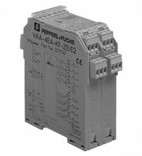
AS-Interface sensor/actuator module VAA-4EA-KF-ZE/E2
- AS-Interface certificate
- Housing with removable, coded terminals
- AS-Interface connection via Power Rail
- Communication monitoring, turn-off
- Outputs loadable up to 8 A (per module)
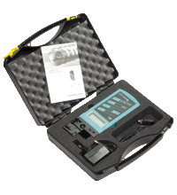
- Addressing jack
- Power supply of outputs from the external auxiliary voltage
- External power supply of sensors
- Function display for bus, ext. auxiliary voltage, inputs and outputs
Please note: All product-related documents, such as certificates, declarations of conformity, etc., which were issued prior to the conversion under the name Pepperl+Fuchs GmbH or Pepperl+Fuchs AG, also apply to Pepperl+Fuchs SE.
Download the complete datasheet as a PDF:
Datasheet excerpt: Technical data of VAA-4EA-KF-ZE/E2
| Product Description |
|---|
| Cabinet module 4 inputs (PNP) and 4 electronic outputs |
| General specifications | ||
|---|---|---|
| Node type | Standard node | |
| AS-Interface specification | V2.0 | |
| Required master specification | ≥ V2.0 | |
| UL File Number | E87056 | |
| Indicators/operating means | ||
| LED PWR/FAULT | dual-LED green/red green: AS-Interface voltage, normal operation red: communication error or address 0 |
|
| LED AUX | ext. auxiliary voltage UAUX ; LED green | |
| LED IN | switching state (input); 4 LED yellow | |
| LED OUT | Switching state (output); 4 LED yellow | |
| Electrical specifications | ||
| Auxiliary voltage (output) | 20 ... 30 V DC PELV | |
| Rated operating voltage | 26.5 ... 31.6 V from AS-Interface | |
| Rated operating current | ≤ 30 mA | |
| Protection class | III | |
| Input | ||
| Number/Type | 4 inputs for 2- or 3-wire sensors (PNP), DC | |
| Supply | external | |
| Switching point | ||
| 0 (unattenuated) | ≤ 2 mA | |
| 1 (attenuated) | ≥ 4 mA | |
| Output | ||
| Number/Type | 4 electronic outputs, PNP | |
| Supply | from external auxiliary voltage UAUX | |
| Current | 2 A per output , 8 A per module | |
| Voltage | ≥ (UAUX - 0.5 V) | |
| Compliance with standards and directives | ||
| Directive conformity | ||
| EMC Directive 89/336/EEC | EN 61326, EN 50295 | |
| Standard conformity | ||
| Electromagnetic compatibility | EN 61000-6-2, EN 61326, EN 50295 | |
| Degree of protection | EN 60529 | |
| Programming instructions | ||
| Profile | S-7.F | |
| IO code | 7 | |
| ID code | F | |
| Data bits (function via AS-Interface) | ||
| D0 | ||
| D1 | ||
| D2 | ||
| D3 | ||
| Parameter bits (programmable via AS-i) | function | |
| P0 | communication monitoring P0 = 1 (default settings), monitoring = ON, i.e. if communication fails, the outputs are de-energised P0 = 0, monitoring = OFF, if communication fails, the outputs maintain their condition |
|
| P1 | not used | |
| P2 | not used | |
| P3 | not used | |
| Ambient conditions | ||
| Ambient temperature | -25 ... 70 °C (-13 ... 158 °F) | |
| Storage temperature | -25 ... 85 °C (-13 ... 185 °F) | |
| Mechanical specifications | ||
| Degree of protection | IP20 | |
| Connection | removable coded terminals, Power Rail | |
| Cable | ||
| Length | max. 30 m (Inputs) | |
| Mass | 170 g | |
| Mounting | DIN mounting rail | |
Classifications
| System | Classcode |
|---|---|
| ECLASS 13.0 | 27242604 |
| ECLASS 12.0 | 27242604 |
| ECLASS 11.0 | 27242604 |
| ECLASS 10.0.1 | 27242604 |
| ECLASS 9.0 | 27242604 |
| ECLASS 8.0 | 27242604 |
| ECLASS 5.1 | 27242604 |
| ETIM 9.0 | EC001599 |
| ETIM 8.0 | EC001599 |
| ETIM 7.0 | EC001599 |
| ETIM 6.0 | EC001599 |
| ETIM 5.0 | EC001599 |
| UNSPSC 12.1 | 39121535 |
Details: VAA-4EA-KF-ZE/E2
Product Documentation: VAA-4EA-KF-ZE/E2
| Brief Instructions | Language | File Type | File Size |
|---|---|---|---|
| Instruction leaflet / Beipackzettel | ALL | 250 KB |
Design / Simulation: VAA-4EA-KF-ZE/E2
| CAD | Language | File Type | File Size |
|---|---|---|---|
| CAD 3-D / CAD 3-D | ALL | STP | 289 KB |
Approvals: VAA-4EA-KF-ZE/E2
| Certificates | Certificate No. | Language | File Type | File Size |
|---|---|---|---|---|
| US CA UL | E87056 | ALL | LINK | --- |
Associated Products: VAA-4EA-KF-ZE/E2
| Accessories | ||||||
|---|---|---|---|---|---|---|
|
||||||
|
||||||
AS-Interface Switch Cabinet Module KE5 – Simple Handling and Improved Manageability

The unique housing design of the new KE5 switch cabinet module enables distinct visibility and simplifies mounting, wiring, and maintenance inside switch cabinets and junction boxes.


 +49 621 776-0