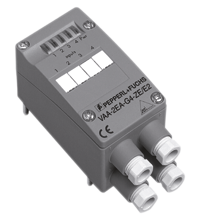
AS-Interface sensor/actuator module VBA-2E2A-G4-ZE/E2
- Degree of protection IP67
- A/B node with extended addressing possibility for up to 62 nodes
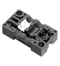
- Flat or round cable connection (via standardized EEMS base, not included with delivery)
- Cable piercing method for flat cable
- Communication monitoring
- Inputs for 2- and 3-wire sensors
- Power supply of outputs from the external auxiliary voltage
- Supply for inputs from AS-Interface
- Function display for bus, inputs and outputs
- LED indicator for overload on sensor supply
- Detection of output overload
Please note: All product-related documents, such as certificates, declarations of conformity, etc., which were issued prior to the conversion under the name Pepperl+Fuchs GmbH or Pepperl+Fuchs AG, also apply to Pepperl+Fuchs SE.
Download the complete datasheet as a PDF:
Datasheet excerpt: Technical data of VBA-2E2A-G4-ZE/E2
| Product Description |
|---|
| G4 module IP67 2 inputs (PNP) and 2 electronic outputs |
| General specifications | ||
|---|---|---|
| Node type | A/B node | |
| AS-Interface specification | V2.1 | |
| Required gateway specification | ≥ V2.1 | |
| UL File Number | E223772 | |
| Indicators/operating means | ||
| LED PWR/FAULT | dual LED green/red green: AS-Interface voltage red: communication error or address 0 green/red flashing: overload sensor supply or outputs |
|
| LED IN | switching state (input); 2 LED yellow | |
| LED OUT | Switching state (output); 2 LED yellow | |
| Electrical specifications | ||
| Auxiliary voltage (output) | 24 V DC ± 15 % PELV | |
| Rated operating voltage | 26.5 ... 31.6 V from AS-Interface | |
| Rated operating current | ≤ 30 mA (without sensors) / max. 140 mA | |
| Protection class | III | |
| Surge protection | UAUX, Uin: Over voltage category III, safe isolated power supplies (PELV) | |
| Input | ||
| Number/Type | 2 inputs for 2- or 3-wire sensors (PNP), DC | |
| Supply | from AS-Interface | |
| Voltage | 21 ... 31 V | |
| Current loading capacity | ≤ 100 mA (TB ≤ 40 °C), ≤ 75 mA (TB ≤ 60 °C), overload-proof and short-circuit protected |
|
| Input current | ≤ 8 mA (limited internally) | |
| Switching point | according to DIN EN 61131-2 (Type 2) | |
| 0 (unattenuated) | ≤ 2 mA | |
| 1 (attenuated) | ≥ 4 mA | |
| Output | ||
| Number/Type | 2 electronic outputs, PNP overload and short-circuit proof | |
| Supply | from external auxiliary voltage UAUX | |
| Voltage | ≥ (UAUX - 0.5 V) | |
| Current | 1 A per output | |
| Directive conformity | ||
| Electromagnetic compatibility | ||
| Directive 2014/30/EU | EN 62026-2:2013 EN 61000-6-2:2001 EN 61000-6-4:2001 | |
| Standard conformity | ||
| Degree of protection | EN 60529:2000 | |
| Input | EN 61131-2:2007 | |
| Emitted interference | EN 61000-6-4:2001 | |
| AS-Interface | EN 62026-2:2013 | |
| Noise immunity | EN 61000-6-2:2001 | |
| Programming instructions | ||
| Profile | S-B.A.0 | |
| IO code | B | |
| ID code | A | |
| ID1 code | 7 | |
| ID2 code | 0 | |
| Data bits (function via AS-Interface) | ||
| D0 | ||
| D1 | ||
| D2 | ||
| D3 | ||
| Parameter bits (programmable via AS-i) | function | |
| P0 | not used | |
| P1 | not used | |
| P2 | not used | |
| P3 | not used | |
| Ambient conditions | ||
| Ambient temperature | -25 ... 60 °C (-13 ... 140 °F) | |
| Storage temperature | -25 ... 85 °C (-13 ... 185 °F) | |
| Relative humidity | 85 % , noncondensing | |
| Climatic conditions | For indoor use only | |
| Altitude | ≤ 2000 m above MSL | |
| Pollution degree | 3 | |
| Mechanical specifications | ||
| Degree of protection | IP67 | |
| Connection | cable piercing method or terminal compartment yellow flat cable/black flat cable or standard round cable inputs/outputs:M12 x 1.5 cable glands and cage tension spring terminals |
|
| Material | ||
| Housing | PA 6 GF30 | |
| Mass | 180 g | |
| Tightening torque, housing screws | 0.8 Nm | |
| Dimensions | ||
| Height | 51 mm | |
| Width | 45 mm | |
| Length | 102 mm | |
| Mounting | DIN rail or screw mounting | |
Classifications
| System | Classcode |
|---|---|
| ECLASS 13.0 | 27242604 |
| ECLASS 12.0 | 27242604 |
| ECLASS 11.0 | 27242604 |
| ECLASS 10.0.1 | 27242604 |
| ECLASS 9.0 | 27242604 |
| ECLASS 8.0 | 27242604 |
| ECLASS 5.1 | 27242604 |
| ETIM 9.0 | EC001599 |
| ETIM 8.0 | EC001599 |
| ETIM 7.0 | EC001599 |
| ETIM 6.0 | EC001599 |
| ETIM 5.0 | EC001599 |
| UNSPSC 12.1 | 39121535 |
Details: VBA-2E2A-G4-ZE/E2
Function
The VBA-2E2A-G4-ZE/E2 AS-Interface module is equipped with 2 inputs and 2 outputs. The inputs permit the connection of mechanical contacts and of 2- and 3-wire sensors, The sensors are supplied via the module. The outputs are electronic outputs, which can be loaded to 24 V DC and 1 A per output.
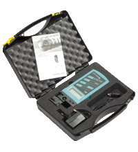
The IP67 rated G4 module is particularly suitable for rough conditions. Sensors and actuators attach to cable glands and cage tension spring terminals thus making the installation especially user-friendly. For pre-addressing the module it can be plugged directly onto the adapter of the hand-held programming device VBP-HH1.
The current switching state of each channel is indicated by an LED, located on the module's top side. In the case of communication errors on the bus, the outputs are de-energised via an integrated watchdog.
Both flat and round cables can be used for the connection of the AS-Interface transmission line and the external 24 V DC power supply. Use the U-G1FF base for the AS-Interface flat cable. The AS-Interface standardised EEMS interface, uses the cable piercing method to connect both the yellow and black flat cables.
Use the U-G1PP base for a round cable. The AS-Interface-cable as well as the external power supply may be connected within the U-G1PP base.
Note:
The device incorporates communication monitoring, which switches off power to the outputs if no communication has taken place on the AS-Interface line for longer than 40 ms.
An overloading of the internal input supply or of the outputs is signalled to the AS-Interface master via the "Peripheral fault" function. Communication via the AS-Interface remains intact.
Product Documentation: VBA-2E2A-G4-ZE/E2
| Brief Instructions | Language | File Type | File Size |
|---|---|---|---|
| Instruction leaflet / Beipackzettel | ALL | 174 KB |
Design / Simulation: VBA-2E2A-G4-ZE/E2
| CAD | Language | File Type | File Size |
|---|---|---|---|
| CAD 3-D / CAD 3-D | ALL | STP | 2960 KB |
| CAD Portal / CAD Portal | ALL | LINK | --- |
Approvals: VBA-2E2A-G4-ZE/E2
| Certificates | Certificate No. | Language | File Type | File Size |
|---|---|---|---|---|
| AS-Interface | 48101 | ALL | 163 KB | |
| Canada, USA UL | CoC 20141115-E223772 | ALL | 342 KB | |
| Declaration of Conformity | ||||
| EU Declaration of Conformity (P+F) / EU-Konformitäterklärung (P+F) | DOC-1008D | ALL | 116 KB | |
| UK Declaration of Conformity (P+F) / UK-Konformitäterklärung (P+F) | DOC-7007 | ALL | 107 KB | |
Associated Products: VBA-2E2A-G4-ZE/E2
| Matching System Components | ||||||
|---|---|---|---|---|---|---|
|
||||||
| Accessories | ||||||
|
||||||
|
||||||
AS-Interface Switch Cabinet Module KE5 – Simple Handling and Improved Manageability

The unique housing design of the new KE5 switch cabinet module enables distinct visibility and simplifies mounting, wiring, and maintenance inside switch cabinets and junction boxes.


 +49 621 776-0