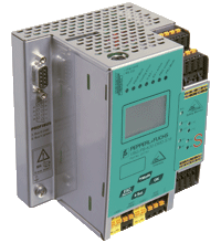
AS-Interface Gateway/Safety Monitor VBG-PB-K30-DMD-S16-C1
- Gateway and safety monitor in one housing
- Connection to PROFIBUS DP
- Certified up to SIL 3 according to IEC 61508 and EN 62061 and up to PLe according to EN 13849
- Memory card for configuration data
- 2 AS-Interface networks
- Integrated data decoupling
- 2 safe output relays and 2 safe electronic outputs
Please note: All product-related documents, such as certificates, declarations of conformity, etc., which were issued prior to the conversion under the name Pepperl+Fuchs GmbH or Pepperl+Fuchs AG, also apply to Pepperl+Fuchs SE.
Download the complete datasheet as a PDF:
Datasheet excerpt: Technical data of VBG-PB-K30-DMD-S16-C1
| Product Description |
|---|
| PROFIBUS Gateway with integrated Safety Monitor, double master for 2 AS-Interface networks |
| General specifications | ||
|---|---|---|
| AS-Interface specification | V3.0 | |
| PLC-Functionality | activateable | |
| Duplicate address detection | from AS-Interface slaves | |
| Earth fault detection | integrated | |
| EMC monitoring | integrated | |
| Diagnostics function | Extended function via display | |
| Data decoupling | integrated | |
| Switch-on delay | < 10 s | |
| Response delay | < 40 ms | |
| UL File Number | E223772 only from low voltage, limited energy source (SELV or PELV) or listed Class 2 source | |
| Functional safety related parameters | ||
| Safety Integrity Level (SIL) | SIL 3 | |
| Performance level (PL) | PL e | |
| MTTFd | 200 a | |
| B10d | 2 E+7 | |
| Indicators/operating means | ||
| Display | Illuminated graphical LC display for addressing and error messages | |
| LED PROFIBUS | PROFIBUS master detected; LED green | |
| LED AS-i ACTIVE | AS-Interface operation normal; LED green | |
| LED CONFIG ERR | configuration error; LED red | |
| LED PRG ENABLE | autom. programming; LED green | |
| LED POWER | voltage ON; LED green | |
| LED PRJ MODE | projecting mode active; LED yellow | |
| LED U AS-i | AS-Interface voltage; LED green | |
| LED AUX | ext. auxiliary voltage UAUX ; LED green | |
| LED EDM/Start | External device monitoring circuit inputs closed, 4x yellow LEDs | |
| LED output circuit | Output circuit closed; 4 x green LEDs | |
| Button | 4 | |
| Electrical specifications | ||
| Insulation voltage | ≥ 500 V | |
| Rated operating voltage | 26.5 ... 31.6 V from AS-Interface; Output K3 and K4 24 V DC | |
| Rated operating current | ≤ 300 mA off AS interface network 1 ≤ 70 mA off AS interface network 2 |
|
| Power supply | max. 4 A per AS-Interface circuit | |
| Interface 1 | ||
| Interface type | RS-485 | |
| Protocol | PROFIBUS DP V1 | |
| Transfer rate | 9.6 kBit/s / 12 MBit/s , Automatic baud rate detection | |
| Interface 2 | ||
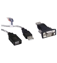
| Interface type | RS 232, serial Diagnostic Interface |
|
| Transfer rate | 19,2 kBit/s | |
| Interface 3 | ||
| Interface type | Chip card slot | |
| Input | ||
| Number/Type | 4 EDM/Start inputs: EDM: Inputs for the external device monitoring circuits Start: start inputs: Static switching current 4 mA at 24 V, dynamic 30 mA at 24 V (T=100 μs) |
|
| Output | ||
| Safety output | Output circuits 1 and 2: 2 potential-free contacts, max. contact load: 3 ADC-13 at 30 VDC, 3 AAC-15 at 30 VAC Output circuits 3 and 4: 2 PNP transistor outputs max. contact load: 0.5 ADC-13 at 30 VDC |
|
| Connection | ||
| PROFIBUS | Sub-D interface | |
| AS-Interface | spring terminals, removable | |
| Directive conformity | ||
| Electromagnetic compatibility | ||
| Directive 2014/30/EU | EN 62026-2:2013 EN 61000-6-2:2005, EN 61000-6-4:2007 | |
| Standard conformity | ||
| Electromagnetic compatibility | EN 61000-6-2:2005, EN 61000-6-4:2007 | |
| Degree of protection | EN 60529:2000 | |
| Fieldbus standard | PROFIBUS according to DIN 19245 Part 3 | |
| AS-Interface | EN 62026-2:2013 | |
| Shock resistance | EN 61131-2:2004 | |
| Standards | EN 61000-6-2:2005, EN 61000-6-4:2007 EN 954-1:1996 (up to Kategorie 4), IEC 61508:2001 and EN 62061:2005 (up to SIL3) EN 13849:2008 (PL e) | |
| Approvals and certificates | ||
| UL approval | An isolated source with a secondary open circuit voltage of ≤ 30 VDC with a 3 A maximum over current protection. Over current protection is not required when a Class 2 source is employed. UL mark does not provide UL certification for any functional safety rating or aspects of the device. |
|
| Ambient conditions | ||
| Ambient temperature | 0 ... 55 °C (32 ... 131 °F) | |
| Storage temperature | -25 ... 85 °C (-13 ... 185 °F) | |
| Mechanical specifications | ||
| Degree of protection | IP20 | |
| Material | ||
| Housing | Stainless steel | |
| Mass | 800 g | |
| Construction type | Low profile housing , Stainless steel | |
Classifications
| System | Classcode |
|---|---|
| ECLASS 13.0 | 27242607 |
| ECLASS 12.0 | 27242607 |
| ECLASS 11.0 | 27242607 |
| ECLASS 10.0.1 | 27242607 |
| ECLASS 9.0 | 27242607 |
| ECLASS 8.0 | 27242607 |
| ECLASS 5.1 | 27242607 |
| ETIM 9.0 | EC001603 |
| ETIM 8.0 | EC001603 |
| ETIM 7.0 | EC001603 |
| ETIM 6.0 | EC001603 |
| ETIM 5.0 | EC001603 |
| UNSPSC 12.1 | 39121004 |
Details: VBG-PB-K30-DMD-S16-C1
Function
The VBG-PB-K30-DMD-S16-C1 is an IP20-rated PROFIBUS gateway with an integral safety monitor and a double master according to AS-Interface specification 3.0. The VBGPB- K30-DMD-S16-C1 has four inputs and four outputs. The four inputs are used either for extended EDM device monitoring or as start inputs. Two sets of two outputs act as relay outputs and switch output circuits 1 and 2 and, as semiconductor outputs, output circuits 3 and 4. Due to integrated decoupling coils, one switching power supply, for example the K24-STR-24...30VDC-10A, can supply 2 AS-Interface lines at the same time. The K30 model is particularly suitable for installation in a control cabinet.
The VBG-PB-K30-DMD-S16-C1 is a combined full-specification AS-Interface PROFIBUS gateway and safety monitor. The product allows a gateway and a safety monitor to be used in a single device. Two safety relays provide a safe interface to the connected consumers. The AS-Interface 3.0 PROFIBUS gateways are used to connect AS-I systems to a higher-level PROFIBUS. They act as a double master for the AS-I segment and as a slave for the PROFIBUS. The AS-I functions are made available on both a cyclic and acyclic basis through PROFIBUSDP V1.
During cyclic data exchange, up to 32 bytes of I/O data (this amount is variable) are transferred as the digital data of an AS-I segment. In addition, analog values as well as the complete command set of the new AS-I specification can be transferred via PROFIBUS using a command interface. Monitoring of the AS-Interface data can be carried out online via PROFIBUS-DP V1 using the serial PROFIBUS master and the AS-I Control Tools. Address assignment, the transfer of the desired configuration and the setting of the Profibus address and baud rate can all be performed using switches. Seven LEDs located on the front panel indicate the current status of the AS-Interface segment. One LED shows the power supply via AUX. A further eight LEDs indicate the status of the inputs and outputs.
Address assignment, the transfer of the desired configuration and the setting of the Profibus address and baud rate can all be performed using switches. Seven LEDs located on the front panel indicate the current status of the AS-Interface segment. One LED shows the power supply via AUX. A further eight LEDs indicate the status of the inputs and outputs. If the AS-Interface gateway has a graphical display, the commissioning of the AS-Interface circuit and testing of the connected peripherals can take place completely separately from the commissioning of PROFIBUS and the programming. Local operation using the graphical display and the four switches allows all the functions covered on the other AS-Interface masters by AS-i Control Tools software to be visualized on the display. An additional RS 232 socket provides a way of exporting data relating to the gateway, network and operation directly from the gateway for extended local diagnosis purposes.
Informative Literature: VBG-PB-K30-DMD-S16-C1
| Literature | Language | File Type | File Size |
|---|---|---|---|
| Application Report - Safe and Efficient AS-Interface Installation at JOTON | ENG | 1990 KB |
Product Documentation: VBG-PB-K30-DMD-S16-C1
| Product information | Language | File Type | File Size |
|---|---|---|---|
| Configuring a Safe Input on AS-Interface Safety at Work | ENG | 258 KB | |
| Manuals | |||
| Manual AS-Interface 3.0 Command Interface | ENG | 3265 KB | |
Design / Simulation: VBG-PB-K30-DMD-S16-C1
| CAD | Language | File Type | File Size |
|---|---|---|---|
| CAD 3-D / CAD 3-D | ALL | STP | 5827 KB |
Approvals: VBG-PB-K30-DMD-S16-C1
| Certificates | Certificate No. | Language | File Type | File Size |
|---|---|---|---|---|
| AS-International Association AS-Interface | 124901 | ALL | 118 KB | |
| US CA UL | E223772 | ALL | LINK | --- |
| Worldwide AS-International Association AS-Interface | 93301 | ALL | 621 KB |
Software: VBG-PB-K30-DMD-S16-C1
| Device Description Files/Drivers | Release Info | File Type | File Size |
|---|---|---|---|
| GSD file VBG-PB-K30-DMD-S16-C1 / GSD-Datei VBG-PB-K30-DMD-S16-C1 | 06/2009 | ZIP | 21 KB |
| Software Tools | |||
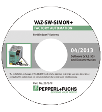
| Diagnostic software - trial version / Diagnose-Software - Testversion | 2013-04 | ZIP | 135082 KB |
| SISTEMA SLB Library AS-Interface Safety / SISTEMA SLB Library AS-Interface Safety | ZIP | 622 KB | |
Associated Products: VBG-PB-K30-DMD-S16-C1
| Accessories | ||||||
|---|---|---|---|---|---|---|
|
||||||
|
||||||


 +49 621 776-0