

Not available for purchase
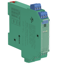
SMART Current Driver KFD2-SCD2-Ex2.LK
- 2-channel isolated barrier
- 24 V DC supply (Power Rail)
- Current output up to 700 Ω load
- HART I/P and valve positioner
- Line fault detection (LFD)
- Accuracy 0.05 %
- Terminal blocks with test sockets
- Up to SIL 2 acc. to IEC 61508


Please note: All product-related documents, such as certificates, declarations of conformity, etc., which were issued prior to the conversion under the name Pepperl+Fuchs GmbH or Pepperl+Fuchs AG, also apply to Pepperl+Fuchs SE.
Download the complete datasheet as a PDF:
Datasheet excerpt: Technical data of KFD2-SCD2-Ex2.LK
| General specifications | ||
|---|---|---|
| Signal type | Analog output | |
| Functional safety related parameters | ||
| Safety Integrity Level (SIL) | SIL 2 | |
| Supply | ||
| Connection | Power Rail or terminals 14+, 15- | |
| Rated voltage | 20 ... 35 V DC | |
| Ripple | within the supply tolerance | |
| Power dissipation | 1.4 W at 20 mA into 10 V (equivalent to 500 Ω) load | |
| Power consumption | 1.8 W at 20 mA | |
| Input | ||
| Connection side | control side | |
| Connection | terminals 7-, 8+, (9+); 10-, 11+, (12+) | |
| Voltage drop | approx. 4 V or internal resistance 200 Ω at 20 mA | |
| Input resistance | > 100 kΩ, when wiring resistance in the field > 16 V (equivalent to 800 Ω at 20 mA) | |
| Current | 4 ... 20 mA limited to approx. 25 mA | |
| Output | ||
| Connection side | field side | |
| Connection | terminals 1+, 2-; 4+, 5- | |
| Voltage | ≥ 14 V at 20 mA | |
| Current | 4 ... 20 mA | |
| Load | 100 ... 700 Ω | |
| Transfer characteristics | ||
| Accuracy | 0.05 % | |
| Deviation | ||
| After calibration | at 20 °C (68 °F): ≤ 10 µA incl. non-linearity, calibration, hysteresis, supply and load changes | |
| Influence of ambient temperature | ≤ 1 µA/K | |
| Rise time | < 100 µs , 10 ... 90 % step change | |
| Galvanic isolation | ||
| Input/power supply | functional insulation, rated insulation voltage 50 V AC | |
| Input/input | functional insulation, rated insulation voltage 50 V AC | |
| Indicators/settings | ||
| Display elements | LEDs | |
| Control elements | DIP switch | |
| Configuration | via DIP switches | |
| Labeling | space for labeling at the front | |
| Directive conformity | ||
| Electromagnetic compatibility | ||
| Directive 2014/30/EU | EN 61326-1:2013 (industrial locations) | |
| Conformity | ||
| Electromagnetic compatibility | NE 21:2011 | |
| Degree of protection | IEC 60529:2001 | |
| Protection against electrical shock | UL 61010-1:2004 | |
| Ambient conditions | ||
| Ambient temperature | -20 ... 60 °C (-4 ... 140 °F) | |
| Mechanical specifications | ||
| Degree of protection | IP20 | |
| Connection | screw terminals | |
| Mass | approx. 150 g | |
| Dimensions | 20 x 124 x 115 mm (0.8 x 4.9 x 4.5 inch) , housing type B2 | |
| Height | 124 mm | |
| Width | 20 mm | |
| Length | 115 mm | |
| Mounting | on 35 mm DIN mounting rail acc. to EN 60715:2001 | |
| Data for application in connection with hazardous areas | ||
| EU-type examination certificate | BAS 00 ATEX 7240 | |
| Marking |  II (1)G [Ex ia Ga] IIC , II (1)D [Ex ia Da] IIIC , I (M1) [Ex ia Ma] I II (1)G [Ex ia Ga] IIC , II (1)D [Ex ia Da] IIIC , I (M1) [Ex ia Ma] I |
|
| Output | [Ex ia Ga] IIC, [Ex ia Da] IIIC, [Ex ia Ma] I | |
| Voltage | 25.2 V | |
| Current | 93 mA | |
| Power | 585 mW | |
| Supply | ||
| Maximum safe voltage | 250 V rms (Attention! The rated voltage can be lower.) | |
| Input | ||
| Maximum safe voltage | 250 V rms (Attention! The rated voltage can be lower.) | |
| Certificate | TÜV 99 ATEX 1499 X | |
| Marking | II 3G Ex nA II T4 [device in zone 2] |
|
| Galvanic isolation | ||
| Input/Output | safe electrical isolation acc. to IEC/EN 60079-11, voltage peak value 375 V | |
| Output/power supply | safe electrical isolation acc. to IEC/EN 60079-11, voltage peak value 375 V | |
| Directive conformity | ||
| Directive 2014/34/EU | EN 60079-0:2012+A11:2013 , EN 60079-11:2012 , EN 60079-15:2010 | |
| International approvals | ||
| UL approval | ||
| Control drawing | 116-0173 (cULus) | |
| IECEx approval | IECEx BAS 04.0014 | |
| Approved for | [Zone 0] [Ex ia] IIC, [Ex iaD], [Ex ia] I | |
| General information | ||
| Supplementary information | Observe the certificates, declarations of conformity, instruction manuals, and manuals where applicable. For information see www.pepperl-fuchs.com. | |
| Accessories | ||
| Optional accessories | - power feed module KFD2-EB2(.R4A.B)(.SP) - universal power rail UPR-03(-M)(-S) - profile rail K-DUCT-BU(-UPR-03) |
|
Classifications
| System | Classcode |
|---|---|
| ECLASS 13.0 | 27210120 |
| ECLASS 12.0 | 27210120 |
| ECLASS 11.0 | 27210120 |
| ECLASS 10.0.1 | 27210120 |
| ECLASS 9.0 | 27210120 |
| ECLASS 8.0 | 27210120 |
| ECLASS 5.1 | 27210120 |
| ETIM 9.0 | EC002653 |
| ETIM 8.0 | EC002653 |
| ETIM 7.0 | EC002653 |
| ETIM 6.0 | EC002653 |
| ETIM 5.0 | EC001485 |
| UNSPSC 12.1 | 32101514 |
Details: KFD2-SCD2-Ex2.LK
Function
This isolated barrier is used for intrinsic safety applications. It drives SMART I/P converters, electrical valves, and positioners in hazardous areas.
Digital signals are superimposed on the analog values at the field or control side and are transferred bi-directionally.
An open and shorted field circuit presents a high input impedance to the control side to allow line fault detection by control system.
If the loop resistance for the digital communication is too low, an internal resistor of 250 Ω between terminals 8, 9 and 11, 12 is available, which may be used as the HART communication resistor.
Terminal 3 (6) is connected to terminal 2 (5) via a 100 Ω resistor. Terminal 3 (6) can be used for an earth leakage connection in combination with the KFD2-ELD-Ex16.
Sockets for the connection of a HART communicator are integrated into the terminals of the device.
A unique collective error messaging feature is available when used with the Power Rail system.
Product Documentation: KFD2-SCD2-Ex2.LK
| Safety and Security Documentation | Language | File Type | File Size |
|---|---|---|---|
| Instruction manual | ENG | 50 KB | |
| Manuals | |||
| Manual | ENG | 3685 KB | |
Design / Simulation: KFD2-SCD2-Ex2.LK
| CAD | Language | File Type | File Size |
|---|---|---|---|
| CAD 3-D / CAD 3-D | ALL | STP | 3048 KB |
| CAD Portal / CAD Portal | ALL | LINK | --- |
| CAE | |||
| EPLAN macro EDZ / EPLAN Makro EDZ | ALL | EDZ | 62 KB |
Approvals: KFD2-SCD2-Ex2.LK
Associated Products: KFD2-SCD2-Ex2.LK
| Accessories | ||||||
|---|---|---|---|---|---|---|
|
||||||
|
||||||
|
||||||
|
||||||
|
||||||
|
||||||
|
||||||
|
||||||
|
||||||


Choose from various selection criteria like safety integrity level, performance level, device function, and signal type and find the SIL/PL assessed device that you are looking for.


Pepperl+Fuchs SE
Lilienthalstraße 200
68307 Mannheim
Germany
info@de.pepperl-fuchs.com
 +49 621 776-0
Pepperl+Fuchs is a leading developer and manufacturer of electronic sensors and components for the global automation market. Continuous innovation, enduring quality, and steady growth have been the foundation of our success for more than 70 years. Pepperl+Fuchs employs 6,300 people worldwide and has manufacturing facilities in Germany, USA, Singapore, Hungary, Indonesia and Vietnam, most of them ISO 9001 certified.