

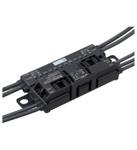

IO-Link Motor Roller Module ICA-8IO-4M4-G20-IO-P14
- Configuration and control via IO-Link
- Connections for 24 V or 48 V DC roller motors
- Inputs for 2- and 3-wire sensors
- Electronic PNP outputs
- Function indicator for motors, inputs and outputs
- Mounting directly in the support profile


Please note: All product-related documents, such as certificates, declarations of conformity, etc., which were issued prior to the conversion under the name Pepperl+Fuchs GmbH or Pepperl+Fuchs AG, also apply to Pepperl+Fuchs SE.
Download the complete datasheet as a PDF:
Datasheet excerpt: Technical data of ICA-8IO-4M4-G20-IO-P14
| Product Description |
|---|
| G20 MDR module with IO-Link for 8 digital inputs/outputs and 4 connections for MDRs (24 V / 48 V) |
| General specifications | ||
|---|---|---|
| UL File Number | E223772 "For use in NFPA 79 Applications only" | |
| MTBF | 90 a | |
| Compatible roller motors | Interroll EC310, Interroll EC5000 24V/48V AI (20W / 35W / 50W), Rulmeca BL3, Itoh Denki PM500XK, Itoh Denki PM500XC , PULSEROLLER Senergy-IDC | |
| Indicators/operating means | ||
| LED yellow/red | IO1 ... IO8: IN, OUT, IO-Link status M1 ... M4: motor status |
|
| Electrical specifications | ||
| Auxiliary voltage | 18 ... 56 V DC PELV Max. 10 A Current limitation of the supply max. 30 A For UL: Z-type miniature circuit breaker in accordance with UL 1077, max. 20 A, required |
|
| Operating voltage | 18 ... 30 V DC, PELV Current limitation of the supply max. 4 A |
|
| No-load supply current | ≤ 25 mA | |
| Operating current | max. 2.5 A | |
| Interface | ||
| Interface type | IO-Link | |
| IO-Link revision | 1.1 | |
| Device profile | Identification and Diagnosis - I&D Firmware update |
|
| Process data | 8 byte inputs (STD/EXT) 6 byte outputs (STD) 18 byte outputs (EXT) |
|
| Vendor ID | 1 (0x0001) | |
| Device ID | 984068 (0x0F0404) (STD) - default 984067 (0x0F0403) (EXT) |
|
| Data transfer rate | COM3 (230.4 kbits/s) | |
| Min. cycle time | 1.2 ms (STD) 2 ms (EXT) |
|
| SIO mode support | no | |
| Compatible master port type | Class A |
|
| Input | ||
| Number/Type | 8 Inputs for 3-wire sensors (PNP), DC (IO1 ... IO8) | |
| Supply | from IO-Link | |
| Current loading capacity | 200 mA per connection IO1/2 ... IO7/8 , overload and short-circuit protected | |
| Input current | ≤ 5 mA (limited internally) | |
| Switching point | Type 3 according to IEC 61131-2 | |
| Output 1 | ||
| Number/Type | 8 electronic outputs, PNP (IO1 … IO8), overload proof and short-circuit proof | |
| Supply | from IO-Link | |
| Current | 200 mA per output | |
| Voltage | ≥ (Ue - 1.5 V) | |
| Output 2 | ||
| Number/Type | 4 outputs for DC roller motors (MOT1 ... MOT4) | |
| Supply | via UPWR | |
| Current loading capacity | 3.5 A (continuous), 5 A (< 2 s), max. 7.5 A (< 0.3 s) per motor Total current (continuous) max. 10 A per device (TB ≤ 50 °C) max. 6 A per device (TB ≤ 60 °C) |
|
| Overload protection | Fuse 4 A, I2t = 122.5 A2s per motor | |
| Signal level | Speed: US = 0.3 … 10 V in no-load operation Ri = 5.6 kΩ, RLOAD ≥ 35 kΩ Direction of rotation: Digital output PNP UD low = high resistance UD high ≥ 12 V Ri = 5.6 kΩ, RLOAD ≥ 15 kΩ |
|
| Fault level | Motor fault: Digital input NPN 0 (no error) ≥ 125 µA 1 (error) ≤ 25 µA |
|
| Directive conformity | ||
| Electromagnetic compatibility | ||
| Directive 2014/30/EU | EN 61326-1:2013 EN 55011:2016 |
|
| Standard conformity | ||
| Degree of protection | EN 60529:2000 | |
| Input | EN 61131-2:2007 | |
| Communication interface | IEC 61131-9 / IO-Link V1.1.3 | |
| Emitted interference | EN 61000-6-4:2007 | |
| Noise immunity | EN 61000-6-2:2005, EN 61326-1:2006 | |
| Approvals and certificates | ||
| UL approval | O1 ... O8 (Output 1): Load specification DC General Use / DC Pilot Duty Degree of protection not tested by UL; tested by Pepperl+Fuchs SE |
|
| Ambient conditions | ||
| Ambient temperature | -25 ... 60 °C (-13 ... 140 °F) | |
| Storage temperature | -25 ... 70 °C (-13 ... 158 °F) | |
| Relative humidity | 85 % non-condensing | |
| Climatic conditions | For indoor use only | |
| Altitude | ≤ 5000 m above MSL | |
| Shock and impact resistance | 30 g, 11 ms in 6 spatial directions, 3 shocks 10 g, 16 ms in 6 spatial directions, 1000 shocks | |
| Vibration resistance | 0.35 mm / 5 g 5 ... 500 Hz | |
| Pollution degree | 2 | |
| Mechanical specifications | ||
| Degree of protection | IP54 according to EN 60529 | |
| Connection | 24 V/48 V power (PWR): Piercing technology, black or gray flat cable IO-Link: M12 round plug connector in accordance with EN 61076-2-101, LM type (4-pin, connector contacts, screw-locking, A-coded) Female connector: LF type or similar Inputs/outputs (IO), motors (MOT): M8 round plug connector in accordance with EN 61076-2-104 IO: LF type (4-pin, bushing contacts, screw-locking, A-coded) Female connector: LM type or similar MOT: NF type (5-pin, bushing contacts, snap-locking, B-coded) Female connector: NM type or similar |
|
| Mass | 390 g | |
| Dimensions | ||
| Height | 27.5 mm | |
| Width | 131.5 mm | |
| Length | 54 mm | |
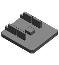
| Mounting | 2 clips with ∅ 8 mm drill hole The module must be secured to a solid, continuous surface using the two lugs |
|
| Cable length | 1 m (IO-Link) 1.5 m (IO1/2, IO7/8), 0.8 m (IO3/4, IO5/6) 1.0 m (MOT1, MOT4); 0.4 m (MOT2, MOT3) max. 10 m |
|
| Note | The flat cable routing is designed for 100 actuation cycles | |
Classifications
| System | Classcode |
|---|---|
| ECLASS 13.0 | 27242602 |
| ECLASS 12.0 | 27242602 |
| ECLASS 11.0 | 27242602 |
| ECLASS 10.0.1 | 27242602 |
| ECLASS 9.0 | 27242602 |
| ECLASS 8.0 | 27242602 |
| ECLASS 5.1 | 27242602 |
| ETIM 9.0 | EC001597 |
| ETIM 8.0 | EC001597 |
| ETIM 7.0 | EC001597 |
| ETIM 6.0 | EC001597 |
| ETIM 5.0 | EC001597 |
| UNSPSC 12.1 | 32151705 |
Details: ICA-8IO-4M4-G20-IO-P14
Function
The ICA-8IO-4M4-G20-IO-P14 intelligent motor control module is a field module with 8 combined sensor inputs or electronic digital outputs. The 4 outputs can be used to control DC roller motors with 24 V or 48 V operating voltage. The outputs are optimized for the types:
-
Interroll EC310
-
Interroll EC5000 24V AI (20W / 35W / 50W)
-
Interroll EC5000 48V (20W / 35W / 50W)
-
Rulmeca BL3
-
Itoh Denki PM500XK
-
Itoh Denki PM500XC
-
PULSEROLLER Senergy-IDC
The compact housing can be mounted directly into support profiles or cable ducts. The power supply U PWR is connectedby piercing technology. The swiveling flat cable guide locks without tools by a snap-fit.
The combined inputs and outputs and the motor outputs are connected using cable outputs with M8 round connectors. The inputs and outputs have 4-pin female connectors with locking nut, the motor outputs have 5-pin snap-on female connectors. IO-Link is connected using a cable output with M12 4-pin round plug connector.The inputs and outputs are supplied via IO-Link. The motor outputs are supplied via U PWR.
The LEDs IO display the current switching state and as well a fault condition of the combined inputs/outputs. The LEDs M display the operating state of the motors (stop/run/fault).
The module is configured via IO-Link.
Informative Literature: ICA-8IO-4M4-G20-IO-P14
| Literature | Language | File Type | File Size |
|---|---|---|---|
| Product Information - Motor Control Modules G20 Series | ENG | 1573 KB |
Product Documentation: ICA-8IO-4M4-G20-IO-P14
| Brief Instructions | Language | File Type | File Size |
|---|---|---|---|
| Commissioning Instructions | ALL | 206 KB | |
| Manuals | |||
| Manual | ENG | 2327 KB | |
| Parameter Information | |||
| IODD for ICA-8IO-4M4-G20-IO-P14 (EXT) | ENG | 512 KB | |
| IODD for ICA-8IO-4M4-G20-IO-P14 (STD) | ENG | 510 KB | |
Design / Simulation: ICA-8IO-4M4-G20-IO-P14
| CAD | Language | File Type | File Size |
|---|---|---|---|
| 3-D | ALL | STP | 3418 KB |
Approvals: ICA-8IO-4M4-G20-IO-P14
| Certificates | Certificate No. | Language | File Type | File Size |
|---|---|---|---|---|
| Canada, USA UL | UL-US-L223772-1D1-52209102-2 | ALL | 282 KB | |
| IO-Link Manufacturer Declaration | CERT-7376 | ALL | 173 KB | |
| Declaration of Conformity | ||||
| EU Declaration of Conformity (Pepperl+Fuchs) | TDOC-7569_ENG | ENG | 197 KB | |
| UK Declaration of Conformity (Pepperl+Fuchs) | TDOC-7571_ENG | ENG | 171 KB | |
Software: ICA-8IO-4M4-G20-IO-P14
| Device Description Files/Drivers | Release Info | File Type | File Size |
|---|---|---|---|
| IODD for ICA-8IO-4M4-G20-IO-P14 (EXT) | V1.00.000 / 2024-04-10 | ZIP | 223 KB |
| IODD for ICA-8IO-4M4-G20-IO-P14 (STD) | V1.00.000 / 2024-04-10 | ZIP | 222 KB |
| Software Tools | |||
| IO-Link Offline Parameterization Tool | V1.00.006 / 2022-07-10 | ZIP | 96138 KB |
Associated Products: ICA-8IO-4M4-G20-IO-P14
| Accessories | ||||||
|---|---|---|---|---|---|---|
|
||||||
|
||||||
|
||||||
|
||||||
|
||||||


Connect your factory floor sensors to the cloud and start your digital transformation with the new IIoT starter kits.


Pepperl+Fuchs SE
Lilienthalstraße 200
68307 Mannheim
Germany
info@de.pepperl-fuchs.com
 +49 621 776-0
Pepperl+Fuchs is a leading developer and manufacturer of electronic sensors and components for the global automation market. Continuous innovation, enduring quality, and steady growth have been the foundation of our success for more than 70 years. Pepperl+Fuchs employs 6,300 people worldwide and has manufacturing facilities in Germany, USA, Singapore, Hungary, Indonesia and Vietnam, most of them ISO 9001 certified.