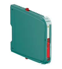
SMART Universal Barrier HiC2441
- 1-channel isolated barrier
- 24 V DC supply (bus powered)
- Analog input, digital input,
analog output, digital output - No configuration required, device is self-adapting
- HART transparency
- Low power dissipation
- 3-way isolation
- Up to SIL 2 acc. to IEC/EN 61508
Please note: All product-related documents, such as certificates, declarations of conformity, etc., which were issued prior to the conversion under the name Pepperl+Fuchs GmbH or Pepperl+Fuchs AG, also apply to Pepperl+Fuchs SE.
De complete datasheet als PDF downloaden:
Technische gegevens HiC2441
| General specifications | ||
|---|---|---|
| Signal type | Universal | |
| Functional safety related parameters | ||
| Safety Integrity Level (SIL) | SIL 2 | |
| Systematic capability (SC) | SC 2 | |
| Supply | ||
| Connection | SL1: 1a, 1b(-); 2a, 2b(+) | |
| Rated voltage | 19 ... 30 V DC bus powered via Termination Board | |
| Ripple | ≤ 10 % | |
| Rated current | ≤ 30 mA | |
| Power consumption | ≤ 700 mW | |
| Analog input | ||
| Suitable field devices | 2-wire SMART transmitters, current sources | |
| Signal | 0/4 ... 20 mA , limited to approx. 40 mA (depends on control system) , reverse polarity protected | |
| Field circuit | SL2: 5a(+), 5b(-) (2-wire SMART transmitter) SL2: 5a(+), 1b(-) (2-wire SMART transmitter with current source) |
|
| Voltage drop | approx. 4 V (current source) | |
| Control circuit | SL1: 8a(+), 7a(-) | |
| Supply voltage | min. 16 V at 20 mA (2-wire SMART transmitter) | |
| Voltage | 15 ... 30 V | |
| Signal | 0/4 ... 20 mA , sink mode , working voltage 15 ... 30 V | |
| Ripple | 20 mV rms | |
| Analog output | ||
| Suitable field devices | I/P converters (positioner), on-site-displays | |
| Signal | 0/4 ... 20 mA | |
| Field circuit | SL2: 5a(+), 5b(-) | |
| Load | 0 ... 650 Ω | |
| Voltage | ≥ 13 V at 20 mA | |
| Ripple | 20 mV rms | |
| Control circuit | SL1: 8a(+), 7a(-) | |
| Voltage | 12 ... 30 V | |
| Signal | 0/4 ... 20 mA | |
| Line fault detection | > 100 kΩ at max. 30 V, with field wiring open | |
| Digital input | ||
| Field circuit | SL2: 5a(+), 1a(-) (NAMUR sensor) SL2: 5a(+), 5b(-) (dry contact) |
|
| Suitable field devices | NAMUR sensors according to IEC/EN 60947-5-6, dry contacts | |
| Signal | 0.1 ... 9 mA , sink mode | |
| Open loop voltage | approx. 10 V DC , 1 kΩ series resistance | |
| Signal | 0.1 ... 9 mA | |
| Control circuit | SL1: 8a(+), 7a(-) | |
| Voltage | 13 ... 30 V | |
| Digital output | ||
| Field circuit | SL2: 5a(+), 5b(-) | |
| Suitable field devices | Solenoid Valve , audible alarm , visual alarm | |
| Drive capability | 12 V / 40 mA at 300 Ω load | |
| Internal resistor | min. 240 Ω | |
| Current | 40 mA | |
| Voltage | 12 V | |
| Current limit | 45 mA | |
| Open loop voltage | approx. 22 V | |
| Control circuit | SL1: 8a(+), 7a(-) | |
| Voltage | 1-signal: 19 ... 30 V DC 0-signal: 0 ... 5 V DC |
|
| Current | 1-signal: 0 ... 45 mA, depending on the output load 0-signal: < 0.1 mA, independent of the output load |
|
| Power dissipation | 1.1 W at 24 V, 300 Ω load (digital output) | |
| Transfer characteristics | ||
| Deviation | at 20 °C (68 °F) ≤ ±20 µA incl. linearity, hysteresis and supply fluctuations at 4 ... 20 mA (analog input, analog output) ≤ ±60 µA incl. linearity, hysteresis and supply fluctuations at 0 ... 45 mA (digital output) |
|
| Influence of ambient temperature | < 2 µA/K (0 ... 70 °C (32 ... 158 °F)) < 3 µA/K (-40 ... 0 °C (-40 ... 32 °F)) |
|
| Switching frequency | ≤ 500 Hz with 50 % duty cycle (digital input, NAMUR sensor) ≤ 5 Hz (digital input, dry contact) ≤ 20 Hz (digital output) |
|
| Frequency range | HART: bandwidth by 0.5 Vpp signal and/or 1 mApp signal 950 ... 2500 Hz (analog input, analog output) | |
| Settling time | ≤ 20 ms (analog input, analog output) ≤ 1 ms (digital input, NAMUR sensor) |
|
| Reaction time | ≤ 5 ms , turn-on/turn-off time (digital output) | |
| Galvanic isolation | ||
| Control/power supply | basic insulation according to IEC/EN 61010-1, rated insulation voltage 60 Veff | |
| Indicators/settings | ||
| Display elements | LED | |
| Labeling | space for labeling at the front | |
| Directive conformity | ||
| Electromagnetic compatibility | ||
| Directive 2014/30/EU | EN 61326-1:2013 (industrial locations) | |
| Conformity | ||
| Electromagnetic compatibility | NE 21:2012 For further information see system description. |
|
| Degree of protection | IEC 60529:2001 | |
| Protection against electrical shock | IEC 61010-1:2010 | |
| Input | EN 60947-5-6:2000 | |
| Ambient conditions | ||
| Ambient temperature | -40 ... 70 °C (-40 ... 158 °F) Observe the temperature range limited by derating, see section derating. |
|
| Storage temperature | -40 ... 85 °C (-40 ... 185 °F) | |
| Relative humidity | 95 % non-condensing | |
| Mechanical specifications | ||
| Degree of protection | IP20 | |
| Mass | approx. 105 g | |
| Dimensions | 12.5 x 106 x 128 mm (0.5 x 4.2 x 5.1 inch) (W x H x D) | |
| Height | 106 mm | |
| Width | 12.5 mm | |
| Depth | 128 mm | |
| Mounting | on termination board | |
| Coding | pin 1 and 4 trimmed For further information see system description. |
|
| Data for application in connection with hazardous areas | ||
| EU-type examination certificate | TÜV 14 ATEX 153522 X | |
| Marking |  II (1)G [Ex ia Ga] IIC II (1)G [Ex ia Ga] IIC  II (1)D [Ex ia Da] IIIC II (1)D [Ex ia Da] IIIC  I (M1) [Ex ia Ma] I I (M1) [Ex ia Ma] I |
|
| Supply | ||
| Maximum safe voltage | 250 V (Attention! The rated voltage can be lower.) | |
| Equipment | SL2: 5a(+), 5b(-) | |
| Voltage | 25.2 V | |
| Current | 110 mA | |
| Power | 693 mW | |
| Internal capacitance | 5.7 nF | |
| Internal inductance | 0 mH | |
| Equipment | SL2: 5a(+), 1b(-) | |
| Voltage | < 28 V | |
| Current | < 115 mA | |
| Voltage | 7.2 V | |
| Current | 0 mA | |
| Power | 0 mW | |
| Internal capacitance | 5.7 nF | |
| Internal inductance | 0 mH | |
| Equipment | SL2: 5a(+), 1a(-) | |
| Voltage | 12.6 V | |
| Current | 13 mA | |
| Power | 41 mW | |
| Internal capacitance | 5.7 nF | |
| Internal inductance | 0 mH | |
| Certificate | TÜV 14 ATEX 153523 X | |
| Marking |  II 3G Ex ec IIC T4 Gc II 3G Ex ec IIC T4 Gc |
|
| Galvanic isolation | ||
| Input/Other circuits | safe electrical isolation acc. to IEC/EN 60079-11, voltage peak value 375 V | |
| Directive conformity | ||
| Directive 2014/34/EU | EN IEC 60079-0:2018+AC:2020 , EN 60079-11:2012 , EN 60079-7:2015+A1:2018 | |
| International approvals | ||
| UL approval | E106378 | |
| Control drawing | 116-0408 (cULus) | |
| IECEx approval | ||
| IECEx certificate | IECEx TUN 15.0004X | |
| IECEx marking | [Ex ia Ga] IIC , [Ex ia Da] IIIC , [Ex ia Ma] I Ex ec IIC T4 Gc |
|
| General information | ||
| Supplementary information | Observe the certificates, declarations of conformity, instruction manuals, and manuals where applicable. For information see www.pepperl-fuchs.com. | |
Classifications
| System | Classcode |
|---|---|
| ECLASS 13.0 | 27210107 |
| ECLASS 12.0 | 27210107 |
| ECLASS 11.0 | 27210107 |
| ECLASS 10.0.1 | 27210107 |
| ECLASS 9.0 | 27210107 |
| ECLASS 8.0 | 27210107 |
| ECLASS 5.1 | 27210107 |
| ETIM 9.0 | EC001485 |
| ETIM 8.0 | EC001485 |
| ETIM 7.0 | EC001485 |
| ETIM 6.0 | EC001485 |
| ETIM 5.0 | EC001485 |
| UNSPSC 12.1 | 32101514 |
Details: HiC2441
Product Documentation: HiC2441
| Safety and Security Documentation | Taal | Bestandstype | Bestandsgrootte |
|---|---|---|---|
| Handleiding | HOL | 164 KB | |
| Functional Safety Manual | ENG | 341 KB | |
| Manuals | |||
| System Manual | ENG | 5438 KB | |
Design / Simulation: HiC2441
| CAD | Taal | Bestandstype | Bestandsgrootte |
|---|---|---|---|
| CAD 3-D / CAD 3-D | ALL | STP | 2770 KB |
| CAD Portal / CAD Portal | ALL | LINK | --- |
| CAE | |||
| CAE EPLAN Data Portal / CAE EPLAN Data Portal | ALL | LINK | --- |
| CAE EPLAN macro EDZ / CAE EPLAN Makro EDZ | ALL | EDZ | 13 KB |
Approvals: HiC2441
| Certificates | Certificaatnummer | Taal | Bestandstype | Bestandsgrootte |
|---|---|---|---|---|
| China SITIIAS CCC Ex Certificate | 2021322316003619 (Singapore) | ALL | 1574 KB | |
| Europe TUV Nord ATEX Category 3 G | TÜV 14 ATEX 153523 X | ALL | 156 KB | |
| Europe TUV Nord II (1) D I (M1) II (1) G | TÜV 14 ATEX 153522 X | ALL | 189 KB | |
| TUV Nord Ex ec IECEx Certificate of Conformity | IECEx TUN 15.0004X | ALL | LINK | --- |
| USA Canada UL Hazardous Location Certificate of Compliance cULus UL E106378 | CoC 20190302 - E106378 RepRef 20190227 | ALL | 250 KB | |
| United Kingdom CML UK-Type Examination Certificate UKEX Category (1) D UKEX Category (1) G UKEX Category (M1) | CML 21UKEX2825X | ALL | 161 KB | |
| Worldwide TUV Nord Functional Safety Certificate | Cert. No. 44 207 13734004 | ALL | 158 KB | |
| Control Drawings | ||||
| Control drawing UL / Control drawing UL | ALL | 130 KB | ||
| Declaration of Conformity | ||||
| EU Declaration of Conformity (P+F) / EU-Konformitäterklärung (P+F) | DOC-1863D | ALL | 82 KB | |
Aanverwante producten: HiC2441
| Accessory of | ||||||
|---|---|---|---|---|---|---|
|
||||||
|
||||||


 +31 73 75 07 107