Ej tillgänglig för köp
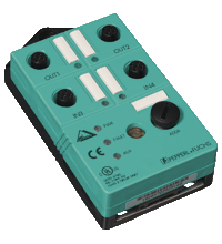
AS-Interface sensor/actuator module VBA-2E2A-G2-ZA/EA2
- AS-Interface certificate
- Degree of protection IP67
- A/B node with extended addressing possibility for up to 62 nodes
- Addressing jack
- Flat cable connection with cable piercing technique, variable flat cable guide
- Communication monitoring
- Inputs for 2-, 3-, and 4-wire sensors
- Power supply of outputs from the external auxiliary voltage
- Supply for inputs from AS-Interface
- Ground connection (FE) possible
- Function display for bus, ext. auxiliary voltage, inputs and outputs
- Detection of overload on sensor supply
- Detection of output overload
Please note: All product-related documents, such as certificates, declarations of conformity, etc., which were issued prior to the conversion under the name Pepperl+Fuchs GmbH or Pepperl+Fuchs AG, also apply to Pepperl+Fuchs SE.
Ladda ned datablad som PDF::
Utdrag ur datablad: Tekniska data för VBA-2E2A-G2-ZA/EA2
| Product Description |
|---|
| G2 flat module 2 inputs (PNP) and 2 electronic outputs |
| General specifications | ||
|---|---|---|
| Node type | A/B node | |
| AS-Interface specification | V2.1 | |
| Required gateway specification | ≥ V2.1 | |
| UL File Number | E223772 | |
| Indicators/operating means | ||
| LED FAULT | error display; LED red red: communication error or address is 0 red flashing: overload of sensor power supply or outputs |
|
| LED PWR | AS-Interface voltage; LED green | |
| LED AUX | ext. auxiliary voltage UAUX ; LED green | |
| LED IN | switching state (input); 2 LED yellow | |
| LED OUT | Switching state (output); 2 LED yellow | |
| Electrical specifications | ||
| Auxiliary voltage (output) | 20 ... 30 V DC PELV | |
| Rated operating voltage | 26.5 ... 31.6 V from AS-Interface | |
| Rated operating current | ≤ 40 mA (without sensors) / max. 140 mA | |
| Protection class | III | |
| Surge protection | UAUX, Uin: Over voltage category III, safe isolated power supplies (PELV) | |
| Input | ||
| Number/Type | 2 inputs for 2- or 3-wire sensors (PNP), DC option 1 input for 4-wire sensor (PNP), DC |
|
| Supply | from AS-Interface | |
| Voltage | 21 ... 31 V | |
| Current loading capacity | ≤ 100 mA (TB ≤ 40 °C), ≤ 75 mA (TB ≤ 60 °C), overload-proof and short-circuit protected |
|
| Input current | ≤ 8 mA (limited internally) | |
| Switching point | according to DIN EN 61131-2 (Type 2) | |
| 0 (unattenuated) | ≤ 2 mA | |
| 1 (attenuated) | ≥ 4 mA | |
| Output | ||
| Number/Type | 2 electronic outputs, PNP overload and short-circuit proof | |
| Supply | from external auxiliary voltage UAUX | |
| Voltage | ≥ (UAUX - 0.5 V) | |
| Current | 1 A per output | |
| Directive conformity | ||
| Electromagnetic compatibility | ||
| Directive 2014/30/EU | EN 62026-2:2013 EN 61000-6-2:2001 EN 61000-6-4:2001 | |
| Standard conformity | ||
| Degree of protection | EN 60529:2000 | |
| Input | EN 61131-2:2007 | |
| Emitted interference | EN 61000-6-4:2001 | |
| AS-Interface | EN 62026-2:2013 | |
| Noise immunity | EN 61000-6-2:2001 | |
| Programming instructions | ||
| Profile | S-B.A.2 | |
| IO code | B | |
| ID code | A | |
| ID1 code | 7 | |
| ID2 code | 2 | |
| Data bits (function via AS-Interface) | ||
| D0 | ||
| D1 | ||
| D2 | ||
| D3 | ||
| Parameter bits (programmable via AS-i) | function | |
| P0 | not used | |
| P1 | not used | |
| P2 | not used | |
| P3 | not used | |
| Ambient conditions | ||
| Ambient temperature | -25 ... 60 °C (-13 ... 140 °F) | |
| Storage temperature | -25 ... 85 °C (-13 ... 185 °F) | |
| Relative humidity | 85 % , noncondensing | |
| Climatic conditions | For indoor use only | |
| Altitude | ≤ 2000 m above MSL | |
| Pollution degree | 3 | |
| Mechanical specifications | ||
| Degree of protection | IP67 | |
| Connection | Cable piercing method flat cable yellow/flat cable black inputs/outputs: M12 round connector |
|
| Material | ||
| Housing | PBT | |
| Mass | 100 g | |
| Tightening torque, cable gland | 0.4 Nm | |
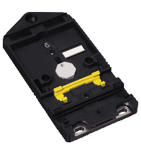
| Mounting | Mounting plate | |
Classifications
| System | Classcode |
|---|---|
| ECLASS 13.0 | 27242604 |
| ECLASS 12.0 | 27242604 |
| ECLASS 11.0 | 27242604 |
| ECLASS 10.0.1 | 27242604 |
| ECLASS 9.0 | 27242604 |
| ECLASS 8.0 | 27242604 |
| ECLASS 5.1 | 27242604 |
| ETIM 9.0 | EC001599 |
| ETIM 8.0 | EC001599 |
| ETIM 7.0 | EC001599 |
| ETIM 6.0 | EC001599 |
| ETIM 5.0 | EC001599 |
| UNSPSC 12.1 | 39121535 |
Details: VBA-2E2A-G2-ZA/EA2
Product Documentation: VBA-2E2A-G2-ZA/EA2
| Brief Instructions | Language | File Type | File Size |
|---|---|---|---|
| Instruction leaflet / Beipackzettel | ALL | 188 KB |
Design / Simulation: VBA-2E2A-G2-ZA/EA2
| CAD | Language | File Type | File Size |
|---|---|---|---|
| CAD 3-D / CAD 3-D | ALL | STP | 149 KB |
| CAD Portal / CAD Portal | ALL | LINK | --- |
Approvals: VBA-2E2A-G2-ZA/EA2
| Certificates | Cert No. | Language | File Type | File Size |
|---|---|---|---|---|
| Canada, USA UL | CoC 20141115-E223772 | ALL | 342 KB | |
| Worldwide AS-International Association AS-Interface | 38701 | ALL | 605 KB | |
| Declaration of Conformity | ||||
| EU Declaration of Conformity (P+F) / EU-Konformitäterklärung (P+F) | DOC-1018C | ALL | 118 KB | |
Associated Products: VBA-2E2A-G2-ZA/EA2
| Matching System Components | ||||||
|---|---|---|---|---|---|---|
|
||||||
| Accessories | ||||||
|
||||||
|
||||||
AS-Interface Switch Cabinet Module KE5 – Simple Handling and Improved Manageability

The unique housing design of the new KE5 switch cabinet module enables distinct visibility and simplifies mounting, wiring, and maintenance inside switch cabinets and junction boxes.


 +46 303 246070