

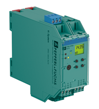
Transmitter Power Supply KFD2-CRG2-Ex1.D
- 1-channel isolated barrier
- 24 V DC supply (Power Rail)
- Input 2-wire and 3-wire transmitters and 2-wire current sources
- Output 0/4 mA ... 20 mA
- 2 relay contact outputs
- Adjustable energized/de-energized delay
- Programmable high/low alarm
- Linearization function (max 20 points)
- Line fault detection (LFD)
- Up to SIL 2 acc. to IEC/EN 61508 / IEC/EN 61511


Please note: All product-related documents, such as certificates, declarations of conformity, etc., which were issued prior to the conversion under the name Pepperl+Fuchs GmbH or Pepperl+Fuchs AG, also apply to Pepperl+Fuchs SE.
Ladda ned datablad som PDF::
Utdrag ur datablad: Tekniska data för KFD2-CRG2-Ex1.D
| General specifications | ||
|---|---|---|
| Signal type | Analog input | |
| Functional safety related parameters | ||
| Safety Integrity Level (SIL) | SIL 2 | |
| Supply | ||
| Connection | Power Rail or terminals 23+, 24- | |
| Rated voltage | 20 ... 30 V DC | |
| Rated current | approx. 130 mA | |
| Power dissipation | 2 W | |
| Power consumption | 2.5 W | |
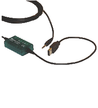
| Interface | ||
| Programming interface | programming socket | |
| Input | ||
| Connection side | field side | |
| Connection | terminals 1, 2, 3 | |
| Input I | ||
| Input signal | 0/4 ... 20 mA | |
| Available voltage | ≥ 15 V at 20 mA | |
| Open circuit voltage/short-circuit current | 24 V / 33 mA | |
| Input resistance | 45 Ω (terminals 2, 3) | |
| Line fault detection | breakage I < 0.2 mA; short-circuit I > 22 mA | |
| Output | ||
| Connection side | control side | |
| Connection | output I: terminals 10, 11, 12 output II: terminals 16, 17, 18 output III: terminals 8+, 7- |
|
| Output signal | 0 ... 20 mA or 4 ... 20 mA | |
| Output I, II | signal, relay | |
| Contact loading | 253 V AC / 2 A / cos φ ≥ 0.7 ; 40 V DC / 2 A | |
| Mechanical life | 5 x 10⁷ switching cycles | |
| Output III | Signal, analog | |
| Current range | 0 ... 20 mA or 4 ... 20 mA | |
| Open loop voltage | max. 24 V DC | |
| Load | max. 650 Ω | |
| Fault signal | downscale I ≤ 3.6 mA, upscale I ≥ 21 mA (acc. NAMUR NE43) | |
| Energized/De-energized delay | 0 ... 250 s , adjustable | |
| Transfer characteristics | ||
| Input I | ||
| Accuracy | < 30 µA | |
| Influence of ambient temperature | 0.003 %/K (30 ppm) | |
| Output I, II | ||
| Response delay | ≤ 200 ms at bounce from 0 ... 20 mA | |
| Output III | ||
| Resolution | ≤ 10 µA | |
| Accuracy | < 20 µA | |
| Influence of ambient temperature | 0.005 %/K (50 ppm) | |
| Reaction time | < 650 ms at bounce from 0 ... 20 mA at the input, 90 % of output full-scale value | |
| Galvanic isolation | ||
| Input/Other circuits | reinforced insulation according to IEC/EN 61010-1, rated insulation voltage 300 Veff | |
| Output I, II/other circuits | reinforced insulation according to IEC/EN 61010-1, rated insulation voltage 300 Veff | |
| Mutual output I, II, III | reinforced insulation according to IEC/EN 61010-1, rated insulation voltage 300 Veff | |
| Output III/power supply and collective error | functional insulation acc. to IEC 62103, rated insulation voltage 50 Veff | |
| Interface/power supply and collective error | functional insulation acc. to IEC 62103, rated insulation voltage 50 Veff | |
| Indicators/settings | ||
| Display elements | LEDs , display | |
| Control elements | Control panel | |
| Configuration | via operating buttons via PACTware |
|
| Labeling | space for labeling at the front | |
| Directive conformity | ||
| Electromagnetic compatibility | ||
| Directive 2014/30/EU | EN 61326-1:2013 (industrial locations) | |
| Low voltage | ||
| Directive 2014/35/EU | EN 61010-1:2010 | |
| Conformity | ||
| Electromagnetic compatibility | NE 21:2006 | |
| Degree of protection | IEC 60529:2001 | |
| Ambient conditions | ||
| Ambient temperature | -20 ... 60 °C (-4 ... 140 °F) | |
| Mechanical specifications | ||
| Degree of protection | IP20 | |
| Connection | screw terminals | |
| Mass | 300 g | |
| Dimensions | 40 x 119 x 115 mm (1.6 x 4.7 x 4.5 inch) (W x H x D) , housing type C2 | |
| Height | 119 mm | |
| Width | 40 mm | |
| Depth | 115 mm | |
| Mounting | on 35 mm DIN mounting rail acc. to EN 60715:2001 | |
| Data for application in connection with hazardous areas | ||
| EU-type examination certificate | TÜV 01 ATEX 1701 | |
| Marking |  II (1)G [Ex ia Ga] IIC II (1)D [Ex ia Da] IIIC I (M1) [Ex ia Ma] I II (1)G [Ex ia Ga] IIC II (1)D [Ex ia Da] IIIC I (M1) [Ex ia Ma] I |
|
| Input | Ex ia | |
| Supply | ||
| Maximum safe voltage | 40 V DC (Attention! The rated voltage can be lower.) | |
| Equipment | terminals 1+, 3- | |
| Voltage | 25.8 V | |
| Current | 93 mA | |
| Power | 0.603 W | |
| Equipment | terminals 2-, 3 | |
| Voltage | < 30 V | |
| Current | 115 mA | |
| Voltage | 5 V | |
| Current | 0.3 mA | |
| Power | 0.3 mW | |
| Equipment | terminals 1+, 2 / 3- | |
| Voltage | 25.8 V | |
| Current | 112 mA | |
| Power | 720 mW | |
| Output I, II | terminals 10, 11, 12; 16, 17, 18 non-intrinsically safe | |
| Maximum safe voltage | 253 V AC / 40 V DC (Attention! Um is no rated voltage.) | |
| Contact loading | 253 V AC/2 A/cos φ > 0.7; 40 V DC/2 A resistive load |
|
| Output III | terminals 8+, 7- non-intrinsically safe | |
| Maximum safe voltage | 40 V (Attention! The rated voltage can be lower.) | |
| Interface | RS 232 | |
| Maximum safe voltage | 40 V (Attention! The rated voltage can be lower.) , RS 232 | |
| Certificate | TÜV 02 ATEX 1885 X | |
| Marking | II 3G Ex nA nC IIC T4 |
|
| Output I, II | ||
| Contact loading | 50 V AC/2 A/cos φ > 0.7; 40 V DC/2 A resistive load | |
| Galvanic isolation | ||
| Input/Other circuits | safe electrical isolation acc. to IEC/EN 60079-11, voltage peak value 375 V | |
| Directive conformity | ||
| Directive 2014/34/EU | EN 60079-0:2012+A11:2013 , EN 60079-11:2012 , EN 60079-15:2010 | |
| International approvals | ||
| FM approval | ||
| Control drawing | 16-554FM-12 (cFMus) | |
| UL approval | E223772 | |
| IECEx approval | ||
| IECEx certificate | IECEx TUN 09.0007 IECEx TSA 18.0007X |
|
| IECEx marking | [Ex ia Ga] IIC, [Ex ia Da] IIIC, [Ex ia Ma] I Ex ec nC IIC T4 Gc |
|
| General information | ||
| Supplementary information | Observe the certificates, declarations of conformity, instruction manuals, and manuals where applicable. For information see www.pepperl-fuchs.com. | |
Classifications
| System | Classcode |
|---|---|
| ECLASS 13.0 | 27210119 |
| ECLASS 12.0 | 27210119 |
| ECLASS 11.0 | 27210119 |
| ECLASS 10.0.1 | 27210119 |
| ECLASS 9.0 | 27210119 |
| ECLASS 8.0 | 27210119 |
| ECLASS 5.1 | 27210119 |
| ETIM 9.0 | EC001485 |
| ETIM 8.0 | EC001485 |
| ETIM 7.0 | EC001485 |
| ETIM 6.0 | EC001485 |
| ETIM 5.0 | EC001485 |
| UNSPSC 12.1 | 32101514 |
Details: KFD2-CRG2-Ex1.D
Informative Literature: KFD2-CRG2-Ex1.D
| Literature | Language | File Type | File Size |
|---|---|---|---|
| Application Report - Biological Cleaning of Wastwater and Secondary Sedimentation Stage | ENG | 566 KB | |
| Application Report - Energy Generation in Wastwater Treatment Plants | ENG | 532 KB | |
| Application Report - Generating Electricity in Coal-Fired Power Plants | ENG | 412 KB | |
| Application Report - Limit Formation in the Interface Level | ENG | 354 KB | |
| Application Report - Sand Trap and Preliminary Sedimentation Stage | ENG | 448 KB | |
| Application Report - Screening Systems in Sewage Treatment Plants | ENG | 577 KB | |
| Application Report - Sicherer Brennstofftransport in Kohlekraftwerken | ENG | 391 KB | |
| Application Report - Water Inlet in Wastewater Treatment Plants | ENG | 526 KB |
Product Documentation: KFD2-CRG2-Ex1.D
| Brief Instructions | Language | File Type | File Size |
|---|---|---|---|
| Operator card KF**-CRG2-**1.D | ALL | 758 KB | |
| Safety and Security Documentation | |||
| Manual | SWE | 164 KB | |
| Functional Safety Manual | ENG | 1936 KB | |
| Manuals | |||
| Manual | ENG | 2313 KB | |
| System Manual | ENG | 3685 KB | |
| Installation and configuration guide Device Type Manager (DTM) | ENG | 8665 KB | |
Design / Simulation: KFD2-CRG2-Ex1.D
| CAD | Language | File Type | File Size |
|---|---|---|---|
| 3-D | ALL | STP | 2719 KB |
| CAD Portal / CAD Portal | ALL | LINK | --- |
| CAE | |||
| CAE EPLAN Data Portal / CAE EPLAN Data Portal | ALL | LINK | --- |
| EPLAN | ALL | EDZ | 2071 KB |
Approvals: KFD2-CRG2-Ex1.D
| Certificates | Cert No. | Language | File Type | File Size |
|---|---|---|---|---|
| Australia Test Safe | ANZEx 17.3006X | ALL | 6788 KB | |
| Brasil TUV Rheinland Brazil | TÜV 13.1155 | ALL | 1234 KB | |
| Canada FM | FM22CA0015X | ALL | 355 KB | |
| Canada USA UL UL E223772 cULus | CoC 20200622 - E223772 RepRef 20071210 | ALL | 82 KB | |
| China SITIIAS CCC Ex Certificate | 2020322316001445 (Singapore) | ALL | 1321 KB | |
| DNV Marine | TAA00001WX | ALL | 106 KB | |
| Europe TUV Nord ATEX Category (1) D ATEX Category (1) G ATEX Category (M1) | TÜV 01 ATEX 1701 | ALL | 577 KB | |
| Europe TUV Nord ATEX Category 3 G | TÜV 02 ATEX 1885X | ALL | 1101 KB | |
| Korea KOSHA | 14-AV4BO-0162 | ALL | 284 KB | |
| South Africa MASC | MASC MS/17-0879 | ALL | 735 KB | |
| TUV Nord IECEx Certificate of Conformity | IECEx TUN 09.0007 | ALL | LINK | --- |
| Test Safe IECEx Certificate of Conformity | IECEx TSA 18.0007X | ALL | LINK | --- |
| USA FM | CoC 3033495 | ALL | 38 KB | |
| United Kingdom CML UK-Type Examination Certificate UKEX Category (1) D UKEX Category (1) G UKEX Category (M1) | CML 22UKEX2503X | ALL | 154 KB | |
| Control Drawings | ||||
| FM Control Drawing | ALL | 153 KB | ||
| Declaration of Conformity | ||||
| EU Declaration of Conformity (Pepperl+Fuchs) | DOC-0023D | ALL | 55 KB | |
Software: KFD2-CRG2-Ex1.D
| Device Description Files/Drivers | Release Info | File Type | File Size |
|---|---|---|---|
| DTM Collection Interface Technology 2 | 1.4.110.77 | ZIP | --- |
| Software Tools | |||
| PACTware 4.1 SP6 | 4.1.0.53 | ZIP | 43327 KB |
| PACTware 5.0 | 5.0.5.31 | ZIP | 44203 KB |
| PACTware 6.X | 6.1 | ZIP | 335938 KB |
Associated Products: KFD2-CRG2-Ex1.D
| Matching System Components | ||||||
|---|---|---|---|---|---|---|
|
||||||
|
||||||
|
||||||
|
||||||
|
||||||
|
||||||
|
||||||
|
||||||
|
||||||
|
||||||
| Accessories | ||||||
|
||||||
|
||||||
|
||||||
|
||||||
|
||||||


Choose from various selection criteria like safety integrity level, performance level, device function, and signal type and find the SIL/PL assessed device that you are looking for.


Pepperl+Fuchs AB
Bultgatan 40 A
442 40 Kungälv
Sverige
orgnr. 556212-2126
info@se.pepperl-fuchs.com
 +46 303 246070
Pepperl+Fuchs is a leading developer and manufacturer of electronic sensors and components for the global automation market. Continuous innovation, enduring quality, and steady growth have been the foundation of our success for more than 70 years. Pepperl+Fuchs employs 6,300 people worldwide and has manufacturing facilities in Germany, USA, Singapore, Hungary, Indonesia and Vietnam, most of them ISO 9001 certified.