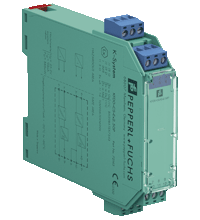
Repeater KFD0-CS-Ex2.50P
- 2-channel isolated barrier
- 24 V DC supply (loop powered)
- Current input/output 4 mA ... 20 mA
- transmitter power supply
- Accuracy 0.1 %
- Reverse polarity protection
- Up to SIL 2 (SC 3) acc. to IEC/EN 61508
Please note: All product-related documents, such as certificates, declarations of conformity, etc., which were issued prior to the conversion under the name Pepperl+Fuchs GmbH or Pepperl+Fuchs AG, also apply to Pepperl+Fuchs SE.
Lataa koko tietolomake PDF-tiedostona:
Ote tietolomakkeesta: Tekniset tiedot KFD0-CS-Ex2.50P
| General specifications | ||
|---|---|---|
| Signal type | Analog input/analog output | |
| Functional safety related parameters | ||
| Safety Integrity Level (SIL) | SIL 2 | |
| Systematic capability (SC) | SC 3 | |
| Supply | ||
| Rated voltage | 5 ... 35 V DC , loop powered | |
| Control circuit | ||
| Connection | terminals 12-, 11+; 8-, 10-, 9+ | |
| Voltage | 5 ... 35 V DC | |
| Current | 4 ... 20 mA | |
| Power dissipation | at 20 mA and Uin < 24.3 V: < 250 mW per channel at 20 mA and Uin > 24.3 V: < 500 mW per channel |
|
| Field circuit | ||
| Connection | terminals 1+, 2-; 4+, 5- | |
| Voltage | for 5V < Uin < 24.3V: ≥ 0.9 x Uin - (0.37 x current in mA) - 1.0 for Uin > 24.3 V: ≥ 21 V - (0.36 x current in mA) |
|
| Short-circuit current | at Uin > 24.3 V : ≤ 65 mA | |
| Transfer current | ≤ 40 mA | |
| Transfer characteristics | ||
| Accuracy | 0.1 % | |
| Deviation | ||
| After calibration | ≤ ± 20 µA; incl. calibration, linearity, hysteresis and load fluctuations at the field side up to a load of 1 kΩ at 20 °C (68 °F) | |
| Influence of ambient temperature | ≤ ± 2 µA/K at Uin ≤ 20 V; ≤ ± 5 µA/K at Uin > 20 V | |
| Rise time | ≤ 5 ms at bounce from 4 ... 20 mA and Uin < 24 V | |
| Galvanic isolation | ||
| Field circuit/control circuit | safe electrical isolation acc. to IEC/EN 60079-11, voltage peak value 375 V | |
| Indicators/settings | ||
| Labeling | space for labeling at the front | |
| Directive conformity | ||
| Electromagnetic compatibility | ||
| Directive 2014/30/EU | EN 61326-1:2013 (industrial locations) | |
| Conformity | ||
| Electromagnetic compatibility | NE 21:2012 EN 61326-3-2:2008 |
|
| Degree of protection | IEC 60529:2001 | |
| Protection against electrical shock | UL 61010-1:2012 | |
| Ambient conditions | ||
| Ambient temperature | -20 ... 70 °C (-4 ... 158 °F) | |
| Mechanical specifications | ||
| Degree of protection | IP20 | |
| Connection | screw terminals | |
| Mass | approx. 100 g | |
| Dimensions | 20 x 107 x 115 mm (0.8 x 4.2 x 4.5 inch) (W x H x D) , housing type B1 | |
| Height | 107 mm | |
| Width | 20 mm | |
| Depth | 115 mm | |
| Mounting | on 35 mm DIN mounting rail acc. to EN 60715:2001 | |
| Data for application in connection with hazardous areas | ||
| EU-type examination certificate | BAS 98 ATEX 7343 X | |
| Marking |  II (1)G [Ex ia Ga] IIC II (1)G [Ex ia Ga] IIC  II (1)D [Ex ia Da] IIIC II (1)D [Ex ia Da] IIIC  I (M1) [Ex ia Ma] I I (M1) [Ex ia Ma] I |
|
| Voltage | 25.2 V | |
| Current | 93 mA | |
| Power | 585 mW | |
| Control circuit | ||
| Maximum safe voltage | 250 V eff (Attention! The rated voltage can be lower.) | |
| Field circuit | ||
| Maximum safe voltage | 250 V eff (Attention! The rated voltage can be lower.) | |
| Certificate | FIDI 22 ATEX 0001 X | |
| Marking |  II 3G Ex ec IIC T4 Gc II 3G Ex ec IIC T4 Gc |
|
| Galvanic isolation | ||
| Field circuit/control circuit | safe electrical isolation acc. to IEC/EN 60079-11, voltage peak value 375 V | |
| Directive conformity | ||
| Directive 2014/34/EU | EN IEC 60079-0:2018 , EN 60079-11:2012 , EN IEC 60079-7:2015+A1:2018 | |
| International approvals | ||
| FM approval | ||
| Control drawing | 116-0437 | |
| UL approval | E106378 | |
| Control drawing | 116-0438 (cULus) | |
| IECEx approval | ||
| IECEx certificate | IECEx BAS 05.0004X IECEx CML 19.0040X |
|
| IECEx marking | [Ex ia Ga] IIC , [Ex ia Da] IIIC , [Ex ia Ma] I Ex ec IIC T4 Gc |
|
| General information | ||
| Supplementary information | Observe the certificates, declarations of conformity, instruction manuals, and manuals where applicable. For information see www.pepperl-fuchs.com. | |
Classifications
| System | Classcode |
|---|---|
| ECLASS 13.0 | 27210120 |
| ECLASS 12.0 | 27210120 |
| ECLASS 11.0 | 27210120 |
| ECLASS 10.0.1 | 27210120 |
| ECLASS 9.0 | 27210120 |
| ECLASS 8.0 | 27210120 |
| ECLASS 5.1 | 27210120 |
| ETIM 9.0 | EC002653 |
| ETIM 8.0 | EC002653 |
| ETIM 7.0 | EC002653 |
| ETIM 6.0 | EC002653 |
| ETIM 5.0 | EC001485 |
| UNSPSC 12.1 | 32101514 |
Details: KFD0-CS-Ex2.50P
Function
This isolated barrier is used for intrinsic safety applications.
The device can be used as a repeater or transmitter power supply for 2-wire transmitters.
This device is loop powered. No additional power supply has to be connected.
Use the technical data to verify that proper voltage is available to the field devices.
Informative Literature: KFD0-CS-Ex2.50P
| Literature | Kieli | Tiedostotyyppi | Tiedoston koko |
|---|---|---|---|
| Application Report - Energy Generation in Wastwater Treatment Plants | ENG | 532 KB | |
| Application Report - Generating Electricity in Coal-Fired Power Plants | ENG | 412 KB | |
| Application Report - Screening Systems in Sewage Treatment Plants | ENG | 577 KB | |
| Application Report - Sicherer Brennstofftransport in Kohlekraftwerken | ENG | 391 KB | |
| Application Report - Water Inlet in Wastewater Treatment Plants | ENG | 526 KB |
Product Documentation: KFD0-CS-Ex2.50P
| Safety and Security Documentation | Kieli | Tiedostotyyppi | Tiedoston koko |
|---|---|---|---|
| Käyttöohje | FIN | 163 KB | |
| Functional Safety Manual | ENG | 1969 KB | |
| Manuals | |||
| Manual | ENG | 3685 KB | |
Design / Simulation: KFD0-CS-Ex2.50P
| CAD | Kieli | Tiedostotyyppi | Tiedoston koko |
|---|---|---|---|
| CAD 3-D / CAD 3-D | ALL | STP | 1854 KB |
| CAD Portal / CAD Portal | ALL | LINK | --- |
| CAE | |||
| EPLAN macro EDZ / EPLAN Makro EDZ | ALL | EDZ | 49 KB |
Approvals: KFD0-CS-Ex2.50P
Liitännäistuotteet: KFD0-CS-Ex2.50P
| Matching System Components | ||||||
|---|---|---|---|---|---|---|
|
||||||
| Accessories | ||||||
|
||||||
|
||||||
|
||||||




 +358 20 7861 290