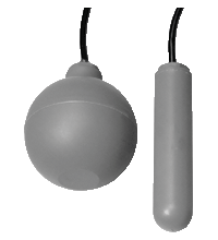
Float Switch LFL1-*K-N-*****
- Switch element: float switch with initiator, mercury-free
- Electrical connections in acc. with NAMUR for hazardous area
- Limit value detection for fluids
- Sleeve design: small diameter, mounting through G1 tap hole possible
- Ball design: high buoyancy
Please note: All product-related documents, such as certificates, declarations of conformity, etc., which were issued prior to the conversion under the name Pepperl+Fuchs GmbH or Pepperl+Fuchs AG, also apply to Pepperl+Fuchs SE.
Téléchargez ici la fiche technique complète en PDF ::
Caractéristiques techniques LFL1-*K-N-*****
| General specifications | ||
|---|---|---|
| Construction type | Inductive sensor with switching ball | |
| Series | LFL1-**-N | |
| Supply | ||
| Rated voltage | 8.2 V ± 2 V | |
| Current consumption | < 1.0 mA unswitched (de-energized at the bottom), > 2.2 mA switched (floated up at the top) |
|
| Reverse polarity protection | yes | |
| Output | ||
| Connection | NAMUR acc. to EN 60947-5-6 , 2-wire | |
| Directive conformity | ||
| Electromagnetic compatibility | ||
| Directive 2014/30/EU | EN 60947-5-2:2007+A1:2012 | |
| Conformity | ||
| Degree of protection | IEC 60529:2001 | |
| Function and system design | ||
| Equipment architecture | A measuring system consists of a float switch LFL1-**-N and a transformer isolated barrier, e. g. KFD2-SR2-Ex1.W. |
|
| Operating conditions | ||
| Installation conditions | ||
| Installation instructions | range of application and minimum length between mounting and float: - PVC version: ≥ 50 mm (2 inch), preferred for water - PUR version: ≥ 100 mm (4 inch), preferred for fuels, heating oils, oily fluids - CSM/CM version: ≥ 100 mm (4 inch), preferred for many acids and lyes mounting: - The float switch is mounted either from sidewards through a cable gland ≥ G1A into the vessel or - by means of a counter weight or rods (e. g. float switch combination) from the top. The pivot of the cable should always be horizontal. |
|
| Process conditions | ||
| Process pressure (static pressure) | sleeve design: ≤ 3 bar at 20 °C (68 °F) ball design: ≤ 2 bar at 20 °C (68 °F) |
|
| Density | sleeve design: ≥ 0.8 g/cm3 ball design: ≥ 0.6 g/cm3 |
|
| Ambient conditions | ||
| Ambient temperature | -20 ... 70 °C (-4 ... 158 °F) | |
| Storage temperature | -25 ... 70 °C (-13 ... 158 °F) | |
| Altitude | ≤ 2000 m above MSL | |
| Mechanical specifications | ||
| Degree of protection | IP68 | |
| Data for application in connection with hazardous areas | ||
| EU-type examination certificate | TÜV 99 ATEX 1407 | |
| Marking |  II 2G Ex ia IIB T5 Gb II 2G Ex ia IIB T5 Gb |
|
| Directive conformity | ||
| Directive 2014/34/EU | EN 60079-0:2012+A11:2013 , EN 60079-11:2012 | |
| Mechanical construction | ||
| Material | float: PP (Polypropylene) cable: - PVC version: PVC cable, highly flexible (2 x 0.75 mm2) - PUR version: PUR cable, highly flexible (2 x 0.50 mm2) - CSM/CM version: CSM/CM cable (chlorinated polyethylene, (2 x 0.75 mm2)) |
|
| Switching point | switch angle, measured against the horizontal: - upper switch point +15° ±5° - lower switch point -15° ±5° |
|
| General information | ||
| Supplementary information | Observe the certificates, declarations of conformity, instruction manuals, and manuals where applicable. For information see www.pepperl-fuchs.com. | |
| Accessories | ||
| Designation | - LFL-Z231, counter nut, G1A, PVC - LFL-Z32, counter weight, grey cast iron with plastic coating (Polycarbonate) - LFL-Z33, counter weight, grey cast iron with ECTFE coating (Halar) - LFL-Z131, gland screw connection G1A, PVC - LFL-Z132, gland screw connection G1A, brass - LFL-Z161, gland screw connection G2A, PVC - LFL-Z431, gland screw connection 1 NPT, PVC - LFL-Z461, gland screw connection 2 NPT, PVC |
|
Classifications
| System | Classcode |
|---|---|
| ECLASS 13.0 | 27200510 |
| ECLASS 12.0 | 27200510 |
| ECLASS 11.0 | 27200510 |
| ECLASS 10.0.1 | 27200510 |
| ECLASS 9.0 | 27200510 |
| ECLASS 8.0 | 27200510 |
| ECLASS 5.1 | 27200510 |
| ETIM 9.0 | EC011178 |
| ETIM 8.0 | EC011178 |
| ETIM 7.0 | EC011178 |
| ETIM 6.0 | EC001447 |
| ETIM 5.0 | EC001447 |
| UNSPSC 12.1 | 41111950 |
Details: LFL1-*K-N-*****
Fonction
L'initiateur (contact NC) est intégré à un flotteur en PP et s'active en cas de déviation de sa position horizontale. La bille de commutation dans le flotteur bouge selon un axe et active le processus de commutation dans l'initiateur de façon inductive. La sortie de commutation fournie par l'initiateur prend la forme d'un signal de commutation conforme à la norme EN 60947-5-6 (NAMUR).
Product Documentation: LFL1-*K-N-*****
| Safety and Security Documentation | Langue | Type de fichier | Taille |
|---|---|---|---|
| Manuel d'instructions | FRA | 129 KB |
Design / Simulation: LFL1-*K-N-*****
| CAD | Langue | Type de fichier | Taille |
|---|---|---|---|
| CAD 3-D / CAD 3-D | ALL | STP | 482 KB |
| CAD 3-D / CAD 3-D | ALL | STP | 254 KB |
Approvals: LFL1-*K-N-*****
| Certificates | Identification | Langue | Type de fichier | Taille |
|---|---|---|---|---|
| Europe TUV Nord ATEX Category 2 G | TÜV 99 ATEX 1407 | ALL | 3475 KB | |
| Declaration of Conformity | ||||
| EU Declaration of Conformity (P+F) / EU-Konformitäterklärung (P+F) | DOC-0580D | ALL | 131 KB | |
| Contamination Declaration | ||||
| Contamination declaration / Kontaminationserklärung | ALL | 137 KB | ||
Produits associés : LFL1-*K-N-*****
| Accessory of | ||||||
|---|---|---|---|---|---|---|
|
||||||
- Demandez à un Expert
- Demande pour une référence équivalente
- Suivi de votre commande en cours
- Nouveautés
- Service Level Agreements for ecom instruments
- Où commander
- Sélection de documentations
- Technologies
- Solutions systèmes de contrôle
- Recherche de documents techniques, catalogues ou brochures
- Articles de presse
- Salons


 +41 32 374 76 76