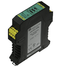
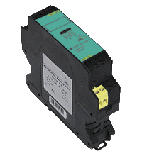
AS-Interface repeater VAR-KE3-TERM
- Minimum delay of signal
- Line lengthening by 100 m (max. 2 repeater in series)
- Galvanic isolation between AS-Interface segments A and B
- No parameterization
- Need no specific address on the AS-Interface bus
- Housing with removable terminals
- The integrated terminator permits up to 200 m network lengths on Segment A
Please note: All product-related documents, such as certificates, declarations of conformity, etc., which were issued prior to the conversion under the name Pepperl+Fuchs GmbH or Pepperl+Fuchs AG, also apply to Pepperl+Fuchs SE.
Download the complete datasheet as a PDF:
Datasheet excerpt: Technical data of VAR-KE3-TERM
| Product Description |
|---|
| AS-Interface advanced repeater with terminator |
| General specifications | ||
|---|---|---|
| AS-Interface specification | V3.0 | |
| Required gateway specification | ≥ V2.0 | |
| UL File Number | E223772 only from low voltage, limited energy source (SELV or PELV) or listed Class 2 source | |
| Functional safety related parameters | ||
| MTTFd | 155 a | |
| Indicators/operating means | ||
| Switch | TERM ON/OFF switches the segment A terminator on/off |
|
| LED FAULT SEG A | Segment A error display; red LED red: communication error |
|
| LED FAULT SEG B | Segment B error display; red LED red: communication error |
|
| LED PWR SEG A | AS interface voltage segment A; green LED | |
| LED PWR SEG B | AS-Interface voltage segment B; green LED | |
| LED TERM | Segment A bus terminator switched on | |
| LED U>26V | Segment A voltage > 26 V | |
| LED U>18,5V | Segment A voltage > 18.5 V | |
| Electrical specifications | ||
| Insulation voltage | ≥ 500 V | |
| Rated operating voltage | 26.5 ... 31.6 V from AS-Interface | |
| Rated operating current | 60 mA (per strand element), 120 mA (total) | |
| Directive conformity | ||
| Electromagnetic compatibility | ||
| Directive 2014/30/EU | EN 62026-2:2013 EN 61000-6-2:2005, EN 61000-6-4:2007 EN 61000-6-3:2001 IEC 62026-2:2008 | |
| Approvals and certificates | ||
| UL approval | An isolated source with a secondary open circuit voltage of ≤ 30 VDC with a 3 A maximum over current protection. Over current protection is not required when a Class 2 source is employed. UL mark does not provide UL certification for any functional safety rating or aspects of the device. | |
| Ambient conditions | ||
| Ambient temperature | 0 ... 55 °C (32 ... 131 °F) | |
| Storage temperature | -25 ... 75 °C (-13 ... 167 °F) | |
| Mechanical specifications | ||
| Degree of protection | IP20 according to EN 60529 | |
| Connection | removable terminals, terminal connection ≤ 2.5 mm2 | |
| Material | ||
| Housing | PA 66-FR | |
| Dimensions | ||
| Height | 99 mm | |
| Width | 22.5 mm | |
| Depth | 114 mm | |
| Mounting | DIN mounting rail | |
Classifications
| System | Classcode |
|---|---|
| ECLASS 13.0 | 27040301 |
| ECLASS 12.0 | 27040301 |
| ECLASS 11.0 | 27040301 |
| ECLASS 10.0.1 | 27040301 |
| ECLASS 9.0 | 27040301 |
| ECLASS 8.0 | 27040301 |
| ECLASS 5.1 | 27040301 |
| ETIM 9.0 | EC001449 |
| ETIM 8.0 | EC001449 |
| ETIM 7.0 | EC001449 |
| ETIM 6.0 | EC001449 |
| ETIM 5.0 | EC002540 |
| UNSPSC 12.1 | 39121535 |
Details: VAR-KE3-TERM
Function
The Advanced-Repeater VAR-KE3-TERM galvanically separates two AS-Interface circuits, and conditions the AS-Interface signals electrically, which extends the cable length by 100 m. The Advanced-Repeater includes a Bus Termination, permitting a line extension of up to 200 m. The Bus Termination is switchable. Two repeaters can be cascaded, resulting in a maximum cable length of 300 m. With one Bus Termination included in line, the maximum circuit extension is up to approximately 600 m.
The Advanced-Repeater features an alignment between sender and receiver that has been optimized even further and offers a shorter delay when the signals pass through the Advanced-Repeater.
The Advanced-Repeater does not require any parameterisation and no own address in the AS-Interface; the overall number of slaves (31 or 62) per branch remains unchanged.
The housing, only 22.5 mm in width, takes up little place in the switch cabinet. The module is mounted by snapping it on to the 35 mm mounting rail in keeping with European standard EN 50022. Pluggable screw terminals are used for connection. This method of mounting permits easy removal during initial operation or servicing.
On account of the galvanic separation, each segment requires a power supply unit or a power extender.
Two LEDs indicate the correct polarity of the AS-Interface cables; two LEDs indicate any communication errors in the respective AS-Interface circuits.
Design / Simulation: VAR-KE3-TERM
| CAD | Language | File Type | File Size |
|---|---|---|---|
| CAD 3-D / CAD 3-D | ALL | STP | 4525 KB |
| CAD Portal / CAD Portal | ALL | LINK | --- |
| CAE | |||
| CAE EPLAN Data Portal / CAE EPLAN Data Portal | ALL | LINK | --- |
| CAE EPLAN macro EDZ / CAE EPLAN Makro EDZ | ALL | EDZ | 1630 KB |
Approvals: VAR-KE3-TERM
| Certificates | Certificate No. | Language | File Type | File Size |
|---|---|---|---|---|
| US CA UL | E223772 | ALL | LINK | --- |
| Declaration of Conformity | ||||
| EU Declaration of Conformity (P+F) / EU-Konformitäterklärung (P+F) | DOC-2454C | ALL | 109 KB | |
Associated Products: VAR-KE3-TERM
| Accessory of | ||||||
|---|---|---|---|---|---|---|
|
||||||
| Accessories | ||||||
|
||||||


 +1 330 425-3555