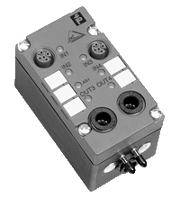
AS-Interface pneumatic module VAA-4E2A-G1-ZE/P-S
- AS-Interface certificate
- Degree of protection IP65
- Flat or round cable connection (via standardized EMS base, not included with delivery)
- Cable piercing method for flat cable
- Inputs for 2- and 3-wire sensors
- Function display for bus, inputs and outputs
- Direct connection of pneumatic cylinders
 in stock
Quantity

Free Shipping

Purchase on Account
Please note: All product-related documents, such as certificates, declarations of conformity, etc., which were issued prior to the conversion under the name Pepperl+Fuchs GmbH or Pepperl+Fuchs AG, also apply to Pepperl+Fuchs SE.
Download the complete datasheet as a PDF:
Datasheet excerpt: Technical data of VAA-4E2A-G1-ZE/P-S
| Product Description |
|---|
| Pneumatic module 4 inputs/2 pneumatic outputs |
| General specifications | ||
|---|---|---|
| Node type | Standard node | |
| Indicators/operating means | ||
| LED AS-i | AS-Interface voltage; LED green | |
| LED IN | switching state (input); 4 LED yellow | |
| LED OUT | Switching state (output); 2 LED yellow | |
| Electrical specifications | ||
| Rated operating voltage | 26.5 ... 31.6 V from AS-Interface | |
| Rated operating current | ≤ 45 mA (without sensors) ≤ 200 mA (complete) |
|
| Input | ||
| Number/Type | 2x 2 inputs for 2- or 3-wire sensors (PNP), DC | |
| Supply | from AS-Interface | |
| Current loading capacity | ≤ 100 mA, short-circuit protected | |
| Switching point | OFF: ≤ 1.5 mA ON: ≥ 5 mA, ≥ 10 V |
|
| Output | ||
| Number/Type | 2 pneumatic outputs with separated 3/2-way valves | |
| Pneumatic output | ||
| Venting guide | Sinter filter | |
| Compressed air | 2 ... 8 bar, filtered (5 µm), oiled or unoiled compressed air | |
| Air throughput | 550 Nl/min at 6/0 bar 350 Nl/min at 6/5 bar Nl = Standard litre |
|
| Valve cross-section | 5 mm | |
| Directive conformity | ||
| Electromagnetic compatibility | ||
| Directive 2014/30/EU | EN 62026-2:2013 | |
| Standard conformity | ||
| Degree of protection | EN 60529:2000 | |
| AS-Interface | EN 62026-2:2013 | |
| Programming instructions | ||
| Profile | S-7.F | |
| IO code | 7 | |
| ID code | F | |
| ID1 code | F | |
| ID2 code | F | |
| Data bits (function via AS-Interface) | ||
| D0 | ||
| D1 | ||
| D2 | ||
| D3 | ||
| Parameter bits (programmable via AS-i) | function | |
| P0 | not used | |
| P1 | not used | |
| P2 | not used | |
| P3 | not used | |
| Ambient conditions | ||
| Ambient temperature | 0 ... 55 °C (32 ... 131 °F) | |
| Storage temperature | -20 ... 85 °C (-4 ... 185 °F) | |
| Mechanical specifications | ||
| Degree of protection | IP65 according to EN 60529 | |
| Connection | cable piercing methos or terminals flat cable or standard round cable inputs: M12 x 1 quick disconnect outputs: plug-in hose connector (8 mm) |
|
| Mass | approx. 200 g | |
| Dimensions | ||
| Height | 60 mm | |
| Width | 45 mm | |
| Length | 102 mm | |
| Mounting | DIN rail or screw mounting | |
Classifications
| System | Classcode |
|---|---|
| ECLASS 13.0 | 27242604 |
| ECLASS 12.0 | 27242604 |
| ECLASS 11.0 | 27242604 |
| ECLASS 10.0.1 | 27242604 |
| ECLASS 9.0 | 27242604 |
| ECLASS 8.0 | 27242604 |
| ECLASS 5.1 | 27242604 |
| ETIM 9.0 | EC001599 |
| ETIM 8.0 | EC001599 |
| ETIM 7.0 | EC001599 |
| ETIM 6.0 | EC001599 |
| ETIM 5.0 | EC001599 |
| UNSPSC 12.1 | 39121535 |
Details: VAA-4E2A-G1-ZE/P-S
Function
The VAA-4E2A-G1-ZE/P-S module features 4 inputs for the connection of 2- or 3-wire sensors and 2 pneumatic outputs with a high air flow rate for direct control of pneumatic drives in the field. 2 separate 3/2-way valves are integrated in the module. Both the valve and the sensors connected to the module are supplied via the bus cable.
The sensors are connected to the module via M12 x 1-circular connectors; the outputs are connected to the pneumatic drive via standard hose plug-in connectors (LEGRIS LF 3000, 8 mm).
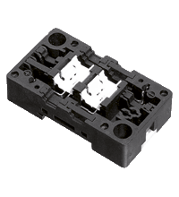
Various bases are available for the module.The U-G1F (or U-G1FA) base provides the connection to the AS-Interface flat cable; the U-G1P base provides the connection to a round cable.
It happens very frequently that output modules must be installed in series with the pneumatic module. If the outputs of the output modules are supplied with external power transferred via a flat cable, a suitable EEMS base (U-G1FF or U-G1FFA) must be used for the pneumatic module. In this case, VAA-4E2A-G1-ZE/P-S accesses the AS-Interface cable instead of the power supply cable.
Note:
The slave address must be programmed before commissioning (default setting
Medium: Filtered (5 μm), oiled or unoiled compressed air (2 ... 8 bars).
Warning:
Dangerous electric voltage can lead to electric shock and burns. The system must be disconnected from the power supply before the beginning of the works.
Product Documentation: VAA-4E2A-G1-ZE/P-S
| Brief Instructions | Language | File Type | File Size |
|---|---|---|---|
| Instruction leaflet / Beipackzettel | ALL | 281 KB |
Design / Simulation: VAA-4E2A-G1-ZE/P-S
| CAD | Language | File Type | File Size |
|---|---|---|---|
| CAD 3-D / CAD 3-D | ALL | STP | 1697 KB |
| CAD Portal / CAD Portal | ALL | LINK | --- |
Approvals: VAA-4E2A-G1-ZE/P-S
| Declaration of Conformity | Certificate No. | Language | File Type | File Size |
|---|---|---|---|---|
| EU Declaration of Conformity (P+F) / EU-Konformitäterklärung (P+F) | DOC-2807B | ALL | 116 KB |
Associated Products: VAA-4E2A-G1-ZE/P-S
| Matching System Components | ||||||
|---|---|---|---|---|---|---|
|
||||||
|
||||||
| Accessories | ||||||
|
||||||
AS-Interface Switch Cabinet Module KE5 – Simple Handling and Improved Manageability

The unique housing design of the new KE5 switch cabinet module enables distinct visibility and simplifies mounting, wiring, and maintenance inside switch cabinets and junction boxes.


 +1 330 425-3555