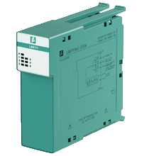
Com Unit for MODBUS TCP LB8111A2-0756
- Interface between the I/O modules and the PCS/PLC
- Com unit for 80 analog or 184 digital channels
- Communication via MODBUS TCP
- Mounting in Zone 2, Class I/Div.2 or in the safe area
- HART communication via MODBUS TCP or service bus
- Configuration via FDT 1.2 DTM
- Non-volatile memory for configuration and parameter settings
- Self configuration in redundant systems
- Permanently self-monitoring
- Outputs drive to safe state in case of failures
- Module can be exchanged under voltage
Please note: All product-related documents, such as certificates, declarations of conformity, etc., which were issued prior to the conversion under the name Pepperl+Fuchs GmbH or Pepperl+Fuchs AG, also apply to Pepperl+Fuchs SE.
Lataa koko tietolomake PDF-tiedostona:
Ote tietolomakkeesta: Tekniset tiedot LB8111A2-0756
| Supply | ||
|---|---|---|
| Connection | backplane bus | |
| Rated voltage | 5 V DC , only in connection with the power supplies LB9*** | |
| Power dissipation | 2.5 W | |
| Power consumption | 2.5 W | |
| Fieldbus connection | ||
| Fieldbus type | MODBUS TCP | |
| Ethernet Interface | ||
| Connection type | RJ-45 , via backplane | |
| Transfer rate | 10 MBit/s | |
| Station connection | directly to PCS or PLC or via hubs or switches | |
| Bus length | max. 100 m (CAT 7 cable) | |
| Addressing | IP address assigned via Ethernet | |
| Ethernet address | IP V4 address (factory standard setting: 0.0.0.0, auto IP, DHCP) | |
| Number of channels per station | max. 80 analog, max. 184 digital | |
| Supported I/O modules | all LB remote I/O modules | |
| HART communication | via Ethernet or service bus | |
| Internal bus | ||
| Connection | backplane bus | |
| Redundancy | via backplane | |
| Service interface | ||
| Connection | 9-pole to RS 485 standard , Sub-D | |
| Number of stations per bus line | 31 (RS-485 standard) | |
| Indicators/settings | ||
| LED indication | LED P: (power supply): On = operating, fast flash = cold start LED 1: (collective alarm): On = internal fault, flashing = no fieldbus connection LED 2: (operating mode): flashing 1 (1:1 ratio) = active, normal operation; flashing 2 (7:1 ratio) = active, simulation LED 3: (status fieldbus): flashing = fieldbus receive channel active LED 4: (status fieldbus): flashing = fieldbus response channel active LED 5: (status service bus): flashing = service bus receive channel active LED 6: (status service bus): flashing = service bus response channel active |
|
| Directive conformity | ||
| Electromagnetic compatibility | ||
| Directive 2014/30/EU | EN 61326-1 | |
| Conformity | ||
| Degree of protection | IEC 60529 | |
| Fieldbus standard | IEEE 802.3 | |
| Environmental test | EN 60068-2-14 | |
| Shock resistance | EN 60068-2-27 | |
| Vibration resistance | EN 60068-2-6 | |
| Damaging gas | EN 60068-2-42 | |
| Relative humidity | EN 60068-2-78 | |
| Ambient conditions | ||
| Ambient temperature | -40 ... 60 °C (-40 ... 140 °F) | |
| Storage temperature | -40 ... 85 °C (-40 ... 185 °F) | |
| Relative humidity | 95 % non-condensing | |
| Altitude | max. 2000 m | |
| Shock resistance | shock type I, shock duration 11 ms, shock amplitude 15 g, number of shocks 18 | |
| Vibration resistance | frequency range 10 ... 150 Hz; transition frequency: 57.56 Hz, amplitude/acceleration ± 0.075 mm/1 g; 10 cycles frequency range 5 ... 100 Hz; transition frequency: 13.2 Hz amplitude/acceleration ± 1 mm/0.7 g; 90 minutes at each resonance |
|
| Damaging gas | designed for operation in environmental conditions acc. to ISA-S71.04-1985, severity level G3 | |
| Mechanical specifications | ||
| Degree of protection | IP20 (module) , mounted on backplane | |
| Connection | via backplane | |
| Mass | approx. 150 g | |
| Dimensions | 32.5 x 100 x 102 mm (1.28 x 3.9 x 4 inch) | |
| Data for application in connection with hazardous areas | ||
| Certificate | PF 08 CERT 1234 X | |
| Marking |  II 3 G Ex nA IIC T4 Gc II 3 G Ex nA IIC T4 Gc |
|
| Directive conformity | ||
| Directive 2014/34/EU | EN IEC 60079-0:2018+AC:2020 , EN 60079-15:2010 | |
| International approvals | ||
| ATEX approval | PF 08 CERT 1234 X | |
| UL approval | E106378 | |
| IECEx approval | ||
| IECEx certificate | IECEx BVS 09.0037X | |
| IECEx marking | Ex nA IIC T4 Gc | |
| General information | ||
| System information | The module has to be mounted in appropriate backplanes (LB9***) in Zone 2 or outside hazardous areas. Here, observe the corresponding declaration of conformity. For use in hazardous areas (e. g. Zone 2, Zone 22 or Div. 2) the module must be installed in an appropriate enclosure. |
|
| Supplementary information | EC-Type Examination Certificate, Statement of Conformity, Declaration of Conformity, Attestation of Conformity and instructions have to be observed where applicable. For information see www.pepperl-fuchs.com. | |
Classifications
| System | Classcode |
|---|---|
| ECLASS 13.0 | 27210121 |
| ECLASS 12.0 | 27210121 |
| ECLASS 11.0 | 27210121 |
| ECLASS 10.0.1 | 27210121 |
| ECLASS 9.0 | 27210121 |
| ECLASS 8.0 | 27210121 |
| ECLASS 5.1 | 27210121 |
| ETIM 9.0 | EC001485 |
| ETIM 8.0 | EC001485 |
| ETIM 7.0 | EC001485 |
| ETIM 6.0 | EC001485 |
| ETIM 5.0 | EC001485 |
| UNSPSC 12.1 | 39121008 |
Details: LB8111A2-0756
Function
The MODBUS TCP com unit forms the interface between the I/O modules on the backplane and the process control system.
It supports all single width and dual width I/O modules. Thereby signals from NAMUR sensors, mechanical contacts, high-power solenoid drivers, power relays, sounders, and alarm LEDs are transported to the higher-level bus system.
The com unit can be easily configured via DTM and supports redundancy as well as HART.
Informative Literature: LB8111A2-0756
| Literature | Kieli | Tiedostotyyppi | Tiedoston koko |
|---|---|---|---|
| Application Report - Communication Redundancy for Uninterrupted Operation | ENG | 529 KB | |
| Application Report - LB and FB Remote I/O Systems for Digitally Connecting Analog Field Devices | ENG | 208 KB | |
| Application Report - Space Saving Extension for Existing Plants | ENG | 300 KB | |
| Application Report - The Modern Whiskey Distillery | ENG | 176 KB | |
| Application Report - Use of Remote I/O in Fluidized Bed Systems | ENG | 222 KB | |
| Application Report - Using Remote I/O Systems for the Efficient Digitalization of Plants | ENG | 371 KB |
Product Documentation: LB8111A2-0756
| System Descriptions | Kieli | Tiedostotyyppi | Tiedoston koko |
|---|---|---|---|
| Supported I/O modules | ENG | 31 KB | |
| Brief Instructions | |||
| Brief Instructions - Firmware update | ENG | 5602 KB | |
| Safety and Security Documentation | |||
| Käyttöohje | FIN | 157 KB | |
| Manuals | |||
| Hardware Manual LB-Remote-I/O-System | ENG | 5385 KB | |
| Manual for LB8107*/FB8207*, LB8111*/FB8211* com unit for MODBUS RTU/TCP | ENG | 6849 KB | |
| Software Information | |||
| Software Product Note Remote I/O DTM / Softwareproduktschein Remote I/O DTM | ALL | 256 KB | |
Design / Simulation: LB8111A2-0756
| CAD | Kieli | Tiedostotyyppi | Tiedoston koko |
|---|---|---|---|
| CAD 3-D / CAD 3-D | ALL | STP | 2098 KB |
Approvals: LB8111A2-0756
| Certificates | Sertifikaatin nro | Kieli | Tiedostotyyppi | Tiedoston koko |
|---|---|---|---|---|
| Bureau Veritas (Maritime) Marine | 22449/C0 BV | ALL | 590 KB | |
| Canada USA UL Certificate of Compliance cULus | CoC 20140904 - E106378 RepRef 20010212 | ALL | 427 KB | |
| China SITIIAS CCC Ex Certificate | 2021322310003601 (Mannheim) | ALL | 4191 KB | |
| DEKRA EXAM IECEx Certificate of Conformity | IECEx BVS 09.0037X | ALL | LINK | --- |
| Europe Pepperl+Fuchs ATEX Category 3 G Certificate of Conformity | PF 08 CERT 1234 X | ALL | 1503 KB | |
| Lloyd's Register Marine | LR2003616TA-02 | ALL | 557 KB | |
| South Africa MASC | MASC MS/20-8438X | ALL | 730 KB | |
| USA UL Certificate of Compliance | UL-US-L106378-47733-21201002-5 RepRef E106378-20010212 | ALL | 252 KB | |
| Declaration of Conformity | ||||
| EU Declaration of Conformity (P+F) / EU-Konformitäterklärung (P+F) | DOC-0522K | ALL | 1040 KB | |
| UK Declaration of Conformity (P+F) / UK-Konformitäterklärung (P+F) | DOC-5793 | ALL | 1036 KB | |
Software: LB8111A2-0756
| Device Description Files/Drivers | Julkaisutiedot | Tiedostotyyppi | Tiedoston koko |
|---|---|---|---|
| DTM MODBUS-TCP Comm. / DTM MODBUS-TCP Comm. | Vers. 2.08pf | ZIP | 19528 KB |
| Firmware | |||
| Firmware for Comm Units 8x11 / Firmware für Buskoppler 8x11 | 7.56 | ZIP | 1615 KB |
| Firmware for Comm Units 8x11 / Firmware für Buskoppler 8x11 | 7.55 | ZIP | 1606 KB |
| Service-Tool / Service-Tool | 3.00.0003 | ZIP | 5185 KB |
| Software Tools | |||
| LB/FB Remote I/O DTM Version 6.8.1 / LB/FB Remote I/O DTM Version 6.8.1 | Version 6.8.1. | ZIP | 40682 KB |
Liitännäistuotteet: LB8111A2-0756
| Accessories | ||||||
|---|---|---|---|---|---|---|
|
||||||


 +358 20 7861 290