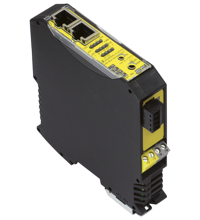
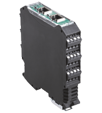
AS-Interface safety module VBA-2E2A-KE4-ENC/SSI-S
- SSI, Sin/Cos, TTL interface
- Safe speed monitoring depending on the position
- Safe position detection
- Integrated safety logic
- Memory card for configuration data
- Up to SIL3 (EN 62061) and PLe (EN13849-1)
Please note: All product-related documents, such as certificates, declarations of conformity, etc., which were issued prior to the conversion under the name Pepperl+Fuchs GmbH or Pepperl+Fuchs AG, also apply to Pepperl+Fuchs SE.
Lataa koko tietolomake PDF-tiedostona:
Ote tietolomakkeesta: Tekniset tiedot VBA-2E2A-KE4-ENC/SSI-S
| Tuotekuvaus |
|---|
| KE4 control cabinet module for rotary encoders 2 safe inputs und 2 safe outputs |
| General specifications | ||
|---|---|---|
| Node type | A/B node | |
| AS-Interface specification | V3.0 | |
| Required gateway specification | ≥ V3.0 | |
| UL File Number | E223772 | |
| Functional safety related parameters | ||
| Safety Integrity Level (SIL) | SIL 3 | |
| Performance level (PL) | PL e | |
| Mission Time (TM) | 20 a | |
| PFHd | 5.08 E-9 | |
| Indicators/operating means | ||
| LED F1, F2 | rotational movement/halt | |
| LED FAULT | error display; LED red red: communication error |
|
| LED ST1, LED ST2 | Status of rotary encoders, 2 yellow LEDs | |
| LED AS-i | AS-Interface voltage; LED green | |
| LED AUX | ext. auxiliary voltage UAUX ; LED green | |
| LED CONF | Dual color-LED, yellow/red, configuration mode | |
| LED O1, O2 | Stauts of outputs | |
| Electrical specifications | ||
| Auxiliary voltage (input) | 18 … 30 VDC | |
| Insulation voltage | 500 V AS-Interface/UAUX: | |
| Rated operating voltage | 18,0 ... 31.6 V from AS-Interface | |
| Rated operating current | ≤ 150 mA from AS-Interface; ≤ 1400 mA from AUX |
|
| Interface 1 | ||
| Interface type | Chip card slot | |
| Input | ||
| Number/Type | 2 inputs for incremental/absolute rotary encoders / 2x RJ45 | |
| Voltage | max. 30 V DC , external | |
| Signal delay | Denpending on frequency, see instruction manual issue "system response time" | |
| Signal frequency | Parameterization range 1 Hz … 250 kHz | |
| Output | ||
| Number/Type | 2 safe electronic outputs | |
| Supply | from external auxiliary voltage UAUX | |
| Voltage | 24 V | |
| Current loading capacity | max contact load: 700 mA DC-13 at 24 V | |
| Directive conformity | ||
| Electromagnetic compatibility | ||
| Directive 2014/30/EU | EN 62026-2:2013 | |
| Standard conformity | ||
| Degree of protection | EN 60529:2000 | |
| Electrical safety | EN 62061:2005 (up to SIL3) EN ISO 13849-1:2008 up to PL e | |
| Input | EN 61131-2:2007 | |
| AS-Interface | EN 62026-2:2013 | |
| Programming instructions | ||
| Profile | Safe input slaves: S-7.B.E. , ID1=F Diagnosis slaves: S-7.A.5., ID1=7 (factory default setting) |
|
| IO code | 7 | |
| ID code | B | |
| ID1 code | E | |
| Ambient conditions | ||
| Ambient temperature | 0 ... 55 °C (32 ... 131 °F) | |
| Storage temperature | -25 ... 85 °C (-13 ... 185 °F) | |
| Mechanical specifications | ||
| Degree of protection | IP20 | |
| Connection | removable terminals rated connection capacity: rigid/flexible (with and without wire-end ferrules): 0.25 mm2 ... 2.5 mm2 for multiple-wire connection with two wires of equal cross-section: flexible with twin wire-end ferrules: 0.5 mm2 ... 1.5 mm2 |
|
| Material | ||
| Housing | PA 66-FR | |
| Dimensions | ||
| Height | 99 mm | |
| Width | 22.5 mm | |
| Length | 113 mm | |
| Mounting | DIN mounting rail | |
Classifications
| System | Classcode |
|---|---|
| ECLASS 13.0 | 27272603 |
| ECLASS 12.0 | 27242604 |
| ECLASS 11.0 | 27242604 |
| ECLASS 10.0.1 | 27242604 |
| ECLASS 9.0 | 27242604 |
| ECLASS 8.0 | 27242604 |
| ECLASS 5.1 | 27242604 |
| ETIM 9.0 | EC001599 |
| ETIM 8.0 | EC001599 |
| ETIM 7.0 | EC001599 |
| ETIM 6.0 | EC001599 |
| ETIM 5.0 | EC001599 |
| UNSPSC 12.1 | 39121535 |
Details: VBA-2E2A-KE4-ENC/SSI-S
Function
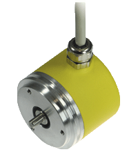
AS-Interface safety module VBA-2E-KE4-ENC/SSI-S is a safe switch cabinet module with two safe inputs and two safe electronic outputs. The inputs can be used to connect devices such as incremental rotary encoders or absolute rotary encoders using SSI, sin/ cos, or TTL interfaces. The main functions of the safety module are: position monitoring, monitoring the speed range and deceleration ramp, safely switching off drives, and providing a safety logic for applications involving up to two axes (STO, SS1, SS2, SLS, SLP, SDI, SCA, etc.).
The housing is only 22.5 mm wide and takes up little space in the switch cabinet. A snapon function mounts the module onto the 35 mm mounting strip in line with EN 50022. An addressing socket is integrated in the module. The AS-Interface and the external power supply (AUX auxiliary voltage) are each connected via a two-way terminal block. This configuration allows the power supply to be easily separated when commissioning or servicing. The AUX auxiliary voltage is used to supply power to the outputs. The rotary encoders are supplied with power independently of the safety module. Yellow LEDs display the current status of the inputs. Communication faults are indicated by red LEDs. A green LED displays the operating voltage and the 0 address.
A chip card stores the configuration data and makes it easy to change the module in case of damage.
Product Documentation: VBA-2E2A-KE4-ENC/SSI-S
| Brief Instructions | Kieli | Tiedostotyyppi | Tiedoston koko |
|---|---|---|---|
| Mounting Instruction VBA-2E2A-KE4-ENC/SSI-S / Montageanleitung VBA-2E2A-KE4-ENC/SSI-S | ALL | 2834 KB | |
| Safety and Security Documentation | |||
| Instruction manual VBA-2E2A-KE4-ENC/SSI-S / Betriebsanleitung VBA-2E2A-KE4-ENC/SSI-S | ALL | 488 KB | |
| Manuals | |||
| Manual VBA-2E*-KE4-ENC* | ENG | 5045 KB | |
Design / Simulation: VBA-2E2A-KE4-ENC/SSI-S
| CAD | Kieli | Tiedostotyyppi | Tiedoston koko |
|---|---|---|---|
| CAD 3-D / CAD 3-D | ALL | STP | 3239 KB |
| CAD Portal / CAD Portal | ALL | LINK | --- |
| CAE | |||
| CAE EPLAN Data Portal / CAE EPLAN Data Portal | ALL | LINK | --- |
| CAE EPLAN macro EDZ / CAE EPLAN Makro EDZ | ALL | EDZ | 38 KB |
Liitännäistuotteet: VBA-2E2A-KE4-ENC/SSI-S
| Matching System Components | ||||||
|---|---|---|---|---|---|---|
|
||||||
| Accessories | ||||||
|
||||||
|
||||||
|
||||||
|
||||||
|
||||||





 +358 20 7861 290