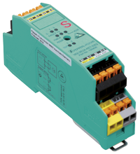
AS-Interface safety module VAA-2E2A-KE1P-S/E2
- 2 safe inputs for mechanical contacts such as EMERGENCY-STOP switch
- Housing with removable terminals
- Communication monitoring
- Power supply of outputs from the external auxiliary voltage
- Power supply of inputs from the module
- Function display for bus, ext. auxiliary voltage, inputs and outputs
- Output overload monitoring
- Switchable internal logic operation of the inputs and outputs via parameter bit
- Addressing jack
Please note: All product-related documents, such as certificates, declarations of conformity, etc., which were issued prior to the conversion under the name Pepperl+Fuchs GmbH or Pepperl+Fuchs AG, also apply to Pepperl+Fuchs SE.
Lataa koko tietolomake PDF-tiedostona:
Ote tietolomakkeesta: Tekniset tiedot VAA-2E2A-KE1P-S/E2
| Tuotekuvaus |
|---|
| KE1-Safety module for the control cabinet 2 safety-related inputs and 2 conventional electronic outputs |
| General specifications | ||
|---|---|---|
| Node type | Safety-Slave | |
| AS-Interface specification | V2.1 | |
| Required gateway specification | ≥ V2.1 | |
| UL File Number | E223772 | |
| Functional safety related parameters | ||
| Safety Integrity Level (SIL) | SIL 3 | |
| Performance level (PL) | PL e | |
| MTTFd | 200 a | |
| PFHd | 0 | |
| PFD | 0 | |
| Indicators/operating means | ||
| LED FAULT | error display; LED red red: communication error or address is 0 red flashing: Output supply overload |
|
| LED PWR | AS-Interface voltage; LED green | |
| LED AUX | ext. auxiliary voltage UAUX ; LED green | |
| LED IN | switching state (input); 2 LED yellow | |
| LED OUT | Switching state (output); 2 LED yellow | |
| Electrical specifications | ||
| Auxiliary voltage (output) | 20 ... 30 V DC PELV |
|
| Rated operating voltage | 26.5 ... 31.6 V from AS-Interface | |
| Rated operating current | ≤ 70 mA | |
| Protection class | III | |
| Surge protection | UAUX, Ue: overvoltage category II, safe isolated power supplies (PELV) | |
| Input | ||
| Number/Type | 2 safety-related inputs for mechanical contacts, crossed-circuit monitored: 2 single-channel contacts: up to category 2/PL c to ISO 13849-1 or 1 2-channel contact: up to category 4/PL e to ISO 13849-1 Cable length must not exceed 300 m per input. |
|
| Supply | from AS-Interface | |
| Voltage | 20 ... 30 V DC pulsed | |
| Current loading capacity | input current limited ≤ 15 mA, overload and short-circuit resistant |
|
| Output | ||
| Number/Type | 2 conventional electronic outputs, PNP | |
| Supply | from external auxiliary voltage UAUX | |
| Voltage | ≥ (UAUX - 0.5 V) | |
| Current | 0.5 A per output | |
| Directive conformity | ||
| Electromagnetic compatibility | ||
| Directive 2014/30/EU | EN 62026-2:2013 EN 61496-1:2004 | |
| Standard conformity | ||
| Insulation coordination | EN 50178:1998 | |
| Electromagnetic compatibility | EN 61000-6-2:2005, EN 61000-4-5:2005 1 kV asymmetric, criterion B, EN 61000-6-4:2007 | |
| Degree of protection | EN 60529:2000 | |
| Fieldbus standard | EN 62026-2:2013 | |
| Electrical safety | EN 50178:1998 IEC 60204-1:2007 | |
| Emitted interference | EN 61000-6-4:2007 | |
| AS-Interface | EN 62026-2:2013 | |
| Functional safety | EN ISO 13849-1:2015 up to PL e, IEC 61508:2010 and IEC 62061:2005/A2:2015 up to SIL 3 | |
| Standards | NFPA 79:2002 | |
| Programming instructions | ||
| Profile | S-7.B | |
| IO code | 7 | |
| ID code | B | |
| ID1 code | F | |
| ID2 code | 0 | |
| Data bits (function via AS-Interface) | ||
| D0 | ||
| D1 | ||
| D2 | ||
| D3 | ||
| Parameter bits (programmable via AS-i) | function | |
| P0 | Logic operation: P0 = 1 (default settings): The outputs are controlled via AS-Interface. P0 = 0: The outputs are controlled via AS-Interface or the inputs. The corresponding output is activated on opening the contacts of an input. |
|
| P1 | not used | |
| P2 | not used | |
| P3 | not used | |
| Ambient conditions | ||
| Ambient temperature | -25 ... 50 °C (-13 ... 122 °F) | |
| Storage temperature | -25 ... 85 °C (-13 ... 185 °F) | |
| Relative humidity | 85 % , noncondensing | |
| Climatic conditions | For indoor use only | |
| Altitude | ≤ 2000 m above MSL | |
| Shock and impact resistance | 10 g, 16 ms in 6 spatial directions 1000 shocks | |
| Vibration resistance | 0.75 mm 10 ... 57 Hz , 5 g 57 ... 150 Hz, 20 cycles | |
| Pollution degree | 2 | |
| Mechanical specifications | ||
| Degree of protection | IP20 | |
| Connection | removable spring terminals Conductor cross-section 0,25 ... 2,5 mm2 |
|
| Material | ||
| Housing | PA 66-FR | |
| Mass | 80 g | |
| Dimensions | ||
| Height | 99.6 mm | |
| Width | 22.5 mm | |
| Length | 48.5 mm | |
| Mounting | DIN mounting rail | |
| Tightening torque of clamping screws | 0.5 Nm ... 0.6 Nm | |
Classifications
| System | Classcode |
|---|---|
| ECLASS 13.0 | 27272603 |
| ECLASS 12.0 | 27242604 |
| ECLASS 11.0 | 27242604 |
| ECLASS 10.0.1 | 27242604 |
| ECLASS 9.0 | 27242604 |
| ECLASS 8.0 | 27242604 |
| ECLASS 5.1 | 27242604 |
| ETIM 9.0 | EC001599 |
| ETIM 8.0 | EC001599 |
| ETIM 7.0 | EC001599 |
| ETIM 6.0 | EC001599 |
| ETIM 5.0 | EC001599 |
| UNSPSC 12.1 | 39121535 |
Details: VAA-2E2A-KE1P-S/E2
Function
The VAA-2E2A-KE1-S/E2 is an AS-Interface safety module with 2 safety-related inputs and 2 conventional outputs. A dual channel mechanical switch or in each case a single channel mechanical switch can be connected to the two safety-related inputs. The outputs are conventional electronic outputs, which may be loaded in total with 1 A (max. 0,5 A per output).
The housing, only 22.5 mm in width and 48.5 mm in height, takes up little place in the switch cabinet. The module features an integrated addressing jack is mounted by snapping onto the 35 mm DIN rail in accordance with EN 50022. Plug-in terminals are used for connection. A 4-way terminal block (black) is used for the inputs. The AS-Interface is connected via a double terminal block (yellow).
The current switching state of each channel is indicated by an LED, located on the module's top side. Similarly, an LED is provided to monitor the AS-Interface communication and to indicate that the module has the address 0. If a communication error occurs, the outputs are de-energized (only P0=1).
When single channel force-directed mechanical switches are connected, up to Performance level c in accordance with EN ISO 13849-1 can be achieved, given the appropriate wiring and selection of switch.
When a two-channel force-directed mechanical switch is connected, up to Performance level e in accordance with EN ISO 13849-1 can be achieved, given the appropriate wiring and selection of switch.
As per approval in accordance with IEC 61508 and IEC 62061 up to SIL 3 can be achieved.
Both inputs of the module are assigned. The two channels of the mechanical switch are monitored for a cross circuit. LEDs are also provided to indicate AS-Interface voltage and external power supply.
Product Documentation: VAA-2E2A-KE1P-S/E2
| Manuals | Kieli | Tiedostotyyppi | Tiedoston koko |
|---|---|---|---|
| Instruction Manual VAA-2E2A-KE1-S/E2 | ENG | 1634 KB |
Approvals: VAA-2E2A-KE1P-S/E2
| Certificates | Sertifikaatin nro | Kieli | Tiedostotyyppi | Tiedoston koko |
|---|---|---|---|---|
| US CA UL | E223772 | ALL | LINK | --- |
| Declaration of Conformity | ||||
| EU-vaatimustenmukaisuusvakuutus | TDOC-4494BFIN | FIN | 194 KB | |
Liitännäistuotteet: VAA-2E2A-KE1P-S/E2
| Accessories | ||||||
|---|---|---|---|---|---|---|
|
||||||
|
||||||
|
||||||


 +358 20 7861 290