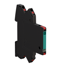
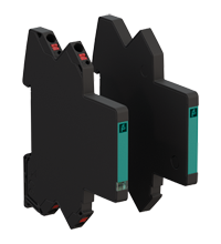
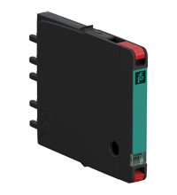
Surge Protection Barrier M-LB-4254
- Surge protection for 2 signal lines
- Nominal voltage 48 V
- Surge protection barrier for grounded signal lines
- Max. surge current (8/20 µs) 20 kA
- Uninterruptable operation (auto reset)
- Status indication
- Modular design, pluggable
- Up to SIL 3 acc. to IEC/EN 61508
Please note: All product-related documents, such as certificates, declarations of conformity, etc., which were issued prior to the conversion under the name Pepperl+Fuchs GmbH or Pepperl+Fuchs AG, also apply to Pepperl+Fuchs SE.
Download the complete datasheet as a PDF:
Datasheet excerpt: Technical data of M-LB-4254
| General specifications | ||
|---|---|---|
| Number of protected signal lines | 2 | |
| Topology | grounded | |
| Functional safety related parameters | ||
| Safety Integrity Level (SIL) | SIL 3 | |
| Electrical specifications | ||
| Connection | protected area: terminals 1', 2' unprotected area: terminals 1, 2 |
|
| Leakage current | < 20 nA bei Uc , line-line < 100 nA bei Uc , line-earth |
|
| Nominal voltage | 48 V | |
| Maximum continuous operating voltage | 38.1 V AC and 54 V DC | |
| Nominal load current | 0.75 A at 70 °C (158 °F) | |
| Series resistance | 1 Ω per line | |
| Impulse discharge current (10/350 µs) | 1.5 kA per line | |
| Nominal discharge current (8/20 µs) | 5 kA per line | |
| Max. surge current (8/20 µs) | 20 kA | |
| Total discharge current (8/20 µs) | 10 kA | |
| Voltage protection level | max. 140 V line-line for nominal discharge current In max. 90 V line-earth for nominal discharge current In |
|
| Impulse reset time | < 30 ms | |
| Cut-off frequency | 5 MHz , line-line | |
| Indicators/settings | ||
| Display elements | status display operating state (green) fault indication (red) |
|
| Conformity | ||
| Degree of protection | IEC 60529:2013 | |
| Functional safety | IEC/EN 61508:2010 | |
| Surge protective devices for low voltage | EN 61643-21:2001+A1:2009+A2:2013 IEC 61643-21:2001+A1:2008+A2:2012 |
|
| Ambient conditions | ||
| Ambient temperature | -40 ... 80 °C (-40 ... 176 °F) | |
| Storage temperature | -40 ... 80 °C (-40 ... 176 °F) | |
| Relative humidity | max. 95 % , without condensation | |
| Corrosion resistance | acc. to ISA-S71.04, severity level G3 | |
| Mechanical specifications | ||
| Degree of protection | IP20 | |
| Connection | spring terminals with push-in connection technology | |
| Core cross section | 0.2 ... 2.5 mm2 one wire 0.2 ... 2.5 mm2 fine-strand |
|
| Material | ||
| Housing | Polyamide PA 6.6 | |
| Mass | approx. 35 g | |
| Dimensions | 6 x 90 x 69 mm (0.24 x 3.5 x 2.7 inch) (W x H x D) | |
| Height | 90 mm | |
| Width | 6 mm | |
| Depth | 69 mm | |
| Mounting | on 35 mm DIN mounting rail acc. to EN 60715:2001 | |
| Data for application in connection with hazardous areas | ||
| Certificate | TÜV 22 ATEX 8881 X | |
| Marking |  II 3G Ex ec IIC T4 Gc II 3G Ex ec IIC T4 Gc |
|
| Temperature class | T4 for ambient temperature ≤ 80 °C | |
| Directive conformity | ||
| Directive 2014/34/EU | EN 60079-0:2018 , EN IEC 60079-7:2015+A1:2018 | |
| International approvals | ||
| UL approval | E501704 | |
| IECEx approval | ||
| IECEx certificate | IECEx TUR 22.0051X | |
| IECEx marking | Ex ec IIC T4 Gc | |
| General information | ||
| Supplementary information | Observe the certificates, declarations of conformity, instruction manuals, and manuals where applicable. For information see www.pepperl-fuchs.com. | |
Classifications
| System | Classcode |
|---|---|
| ECLASS 13.0 | 27171202 |
| ECLASS 12.0 | 27171202 |
| ECLASS 11.0 | 27130805 |
| ECLASS 10.0.1 | 27130805 |
| ECLASS 9.0 | 27130805 |
| ECLASS 8.0 | 27130805 |
| ECLASS 5.1 | 27130801 |
| ETIM 9.0 | EC000941 |
| ETIM 8.0 | EC000941 |
| ETIM 7.0 | EC000941 |
| ETIM 6.0 | EC000941 |
| ETIM 5.0 | EC000941 |
| UNSPSC 12.1 | 39121610 |
Details: M-LB-4254
Function
The device limits induced transients of different causes, e. g. lightning or switching operations. The limitation is achieved by diverting the current to earth and limiting the signal loop voltage during the duration of the overvoltage pulse.
The device consists of base module and protection module.The protection module can be replaced without tools.
The device has a status indication at the front.
The device is mounted on a 35 mm DIN mounting rail according to EN 60715.
Product Documentation: M-LB-4254
| Brief Instructions | Language | File Type | File Size |
|---|---|---|---|
| Instruction leaflet / Beipackzettel | ALL | 5479 KB | |
| Safety and Security Documentation | |||
| Functional Safety Manual | ENG | 1990 KB | |
Design / Simulation: M-LB-4254
| CAD | Language | File Type | File Size |
|---|---|---|---|
| CAD 3-D / CAD 3-D | ALL | STP | 2772 KB |
| CAE | |||
| CAE EPLAN Data Portal / CAE EPLAN Data Portal | ALL | LINK | --- |
| CAE EPLAN macro EDZ / CAE EPLAN Makro EDZ | ALL | EDZ | 1886 KB |
Approvals: M-LB-4254
| Certificates | Certificate No. | Language | File Type | File Size |
|---|---|---|---|---|
| China CNEX CCC Ex Certificate | 2023312304001609 (DEHN SE) | ALL | 931 KB | |
| EU ATEX Category 3 G | TÜV 22 ATEX 8881 X | ALL | 187 KB | |
| TUV Rheinland | IECEx TUR 22.0051X | ALL | LINK | --- |
| USA UL | UL E501704 | ALL | 533 KB | |
| Declaration of Conformity | ||||
| EU Declaration of Conformity (P+F) | TDOC-7118_ENG | ENG | 186 KB | |
Associated Products: M-LB-4254
| Matching System Components | ||||||
|---|---|---|---|---|---|---|
|
||||||
| Accessories | ||||||
|
||||||
|
||||||
- Ask an Expert
- Cross Reference Request
- Check order status
- News
- NetPartner Login
- Subscribe to Gate-Way, our Process Automation Division e-newsletter
- Service Level Agreements for ecom instruments
- Find a Local Distributor or Representative
- Literature
- Technologies
- Control System Solutions
- Download Technical Documents
- Press Releases
- International Trade Shows


 +1 330 425-3555