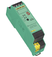
AS-Interface safety module VAA-2E-KE1-S
- 2 safe inputs for mechanical contacts such as EMERGENCY-STOP switch
- Housing with removable terminals
- Communication monitoring
- Power supply of inputs from the module
- Function display for bus and inputs
- Cross-circuit detection
- Addressing jack
 in stock
Quantity

Free Shipping

Purchase on Account
Please note: All product-related documents, such as certificates, declarations of conformity, etc., which were issued prior to the conversion under the name Pepperl+Fuchs GmbH or Pepperl+Fuchs AG, also apply to Pepperl+Fuchs SE.
Download the complete datasheet as a PDF:
Datasheet excerpt: Technical data of VAA-2E-KE1-S
| Product Description |
|---|
| KE1 safety module for the control cabinet, 2 Safety-related inputs |
| General specifications | ||
|---|---|---|
| Node type | Safety node | |
| AS-Interface specification | V2.11 | |
| Required gateway specification | ≥ V2.0 | |
| Profile | S-0.B | |
| IO code | 0 | |
| ID code | B | |
| ID1 code | F | |
| ID2 code | 0 | |
| UL File Number | E87056 | |
| Functional safety related parameters | ||
| Safety Integrity Level (SIL) | SIL 3 / PL e | |
| MTTFd | 200 a | |
| Indicators/operating means | ||
| LED FAULT | error display; LED red red: communication error or address is 0 |
|
| LED PWR | AS-Interface voltage; LED green | |
| LED IN | switching state (input); 2 LED yellow | |
| Electrical specifications | ||
| Rated operating voltage | 26.5 ... 31.6 V PELV from AS-Interface | |
| Rated operating current | ≤ 70 mA | |
| Protection class | III | |
| Input | ||
| Number/Type | 2 safety-related inputs for mechanical contacts, cross-circuit monitored: 2 single-channel contacts: up to category 2 / PL c according to EN ISO 13849-1 or 1 two-channel contact: up to category 4 / PL e according to EN ISO 13849-1 Cable length must not exceed 300 m per input. |
|
| Supply | from AS-Interface | |
| Voltage | 20 ... 30 V DC pulsed | |
| Current loading capacity | input current limited ≤ 15 mA, overload and short-circuit resistant |
|
| Directive conformity | ||
| Electromagnetic compatibility | ||
| Directive 2014/30/EU | EN 62026-2:2013+A1:2019 | |
| Standard conformity | ||
| Insulation coordination | EN 50178:1998 | |
| Electromagnetic compatibility | EN 61000-6-2, EN 61000-4-5 1 kV asymmetric, criterion B, EN 61000-6-4 | |
| Degree of protection | EN 60529:2000 | |
| Fieldbus standard | EN 62026-2:2013+A1:2019 | |
| Electrical safety | EN 50178:1998 IEC 60204-1:2007 | |
| Emitted interference | EN 61000-6-4:2001 | |
| AS-Interface | EN 62026-2:2013 | |
| Functional safety | Category 4 / PL e to EN ISO 13849-1:2015 SIL 3 according to IEC 62061:2015 and IEC 61508 Part 1-7:2010 |
|
| Standards | NFPA 79:2002 | |
| Ambient conditions | ||
| Ambient temperature | -25 ... 50 °C (-13 ... 122 °F) | |
| Storage temperature | -25 ... 85 °C (-13 ... 185 °F) | |
| Shock and impact resistance | 10 g, 16 ms in 6 spatial directions 1000 shocks | |
| Vibration resistance | 0.75 mm 10 ... 57 Hz , 5 g 57 ... 150 Hz, 20 cycles | |
| Mechanical specifications | ||
| Degree of protection | IP20 | |
| Connection | removable terminals, terminal connection ≤ 2.5 mm2 | |
| Material | ||
| Housing | PA 66-FR | |
| Mass | 80 g | |
| Dimensions | ||
| Height | 99.6 mm | |
| Width | 22.5 mm | |
| Length | 48.5 mm | |
| Mounting | DIN mounting rail | |
Classifications
| System | Classcode |
|---|---|
| ECLASS 13.0 | 27272603 |
| ECLASS 12.0 | 27242604 |
| ECLASS 11.0 | 27242604 |
| ECLASS 10.0.1 | 27242604 |
| ECLASS 9.0 | 27242604 |
| ECLASS 8.0 | 27242604 |
| ECLASS 5.1 | 27242604 |
| ETIM 9.0 | EC001599 |
| ETIM 8.0 | EC001599 |
| ETIM 7.0 | EC001599 |
| ETIM 6.0 | EC001599 |
| ETIM 5.0 | EC001599 |
| UNSPSC 12.1 | 39121535 |
Details: VAA-2E-KE1-S
Function
The VAA-2E-KE1-S is an AS-Interface safety module with 2 safety-related inputs. A dual channel mechanical switch or in each case a single channel mechanical switch can be connected to the two inputs.
The housing, only 22.5 mm in width and 48.5 mm in height, takes up little place in the switch cabinet. The module features an integrated addressing jack is mounted by snapping onto the 35 mm DIN rail in accordance with EN 50022. Plug-in terminals are used for connection. A 4-way terminal block (black) is used for the inputs. The AS-Interface is connected via a double terminal block (yellow).
The current switching state of each channel is indicated by an LED, located on the module's top side. Similarly, an LED is provided to monitor the AS-Interface communication and to indicate that the module has the address 0.
When single channel force-directed mechanical switches are connected, up to Category 2 / PL c in accordance with EN ISO 13849-1 can be achieved, given the appropriate wiring and selection of switch.
When a two-channel force-directed mechanical switch is connected, up to Category 4 / PL e in accordance with EN ISO 13849-1 can be achieved, given the appropriate wiring and selection of switch.
As per approval in accordance with IEC 61508 up to SIL 3 can be achieved.
Both inputs of the module are assigned. The two channels of the mechanical switch are monitored for a cross circuit. A LED is also provided to indicate AS-Interface voltage.
Product Documentation: VAA-2E-KE1-S
| Brief Instructions | Language | File Type | File Size |
|---|---|---|---|
| Brief instructions | ENG | 850 KB |
Design / Simulation: VAA-2E-KE1-S
| CAD | Language | File Type | File Size |
|---|---|---|---|
| CAD 3-D / CAD 3-D | ALL | STP | 317 KB |
| CAD Portal / CAD Portal | ALL | LINK | --- |
| CAE | |||
| CAE EPLAN Data Portal / CAE EPLAN Data Portal | ALL | LINK | --- |
| CAE EPLAN macro EDZ / CAE EPLAN Makro EDZ | ALL | EDZ | 35 KB |
Approvals: VAA-2E-KE1-S
| Certificates | Certificate No. | Language | File Type | File Size |
|---|---|---|---|---|
| AS-Interface | 61701 | ALL | 88 KB | |
| Canada, USA UL | CoC 20141115-E223772 | ALL | 342 KB | |
| Declaration of Conformity | ||||
| EU-Declaration of conformity | TDOC-2909CENG | ENG | 196 KB | |
Software: VAA-2E-KE1-S
| Software Tools | Release Info | File Type | File Size |
|---|---|---|---|
| SISTEMA SLB Library AS-Interface Safety / SISTEMA SLB Library AS-Interface Safety | ZIP | 622 KB |
Associated Products: VAA-2E-KE1-S
| Accessories | ||||||
|---|---|---|---|---|---|---|
|
||||||
|
||||||
|
||||||


 +1 330 425-3555