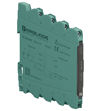
Trip amplifier S1SD-1AI-1R
- 1-channel signal conditioner
- 24 V DC supply
- Input bipolar current and voltage sources
- Input 2-wire and 3-wire transmitters
- Relay contact output
- Restart inhibit
- One-shot function
- Configurable by DIP switches and software
- Connection via screw terminals
Please note: All product-related documents, such as certificates, declarations of conformity, etc., which were issued prior to the conversion under the name Pepperl+Fuchs GmbH or Pepperl+Fuchs AG, also apply to Pepperl+Fuchs SE.
Last ned komplett datablad som PDF:
Datablad utdrag: Tekniske data for S1SD-1AI-1R
| General specifications | ||
|---|---|---|
| Signal type | Analog input | |
| Supply | ||
| Connection | Power Bus or terminals 1-, 2+ | |
| Rated voltage | 16.8 ... 31.2 V DC | |
| Power dissipation | 0.6 W | |
| Power consumption | 0.8 W | |
| Interface | ||
| Programming interface | programming socket | |
| Input | ||
| Connection side | field side | |
| Transmission range | linearity range: unipolar -1 ... 110 % bipolar -110 ... 110 % |
|
| Input I | ||
| Connection | terminals 5, 6, 7- | |
| Input signal | 0/4 ... 20 mA , 0/2 ... 10 mA , ± 10 mA, ± 20 mA , max. 50 mA | |
| Input resistance | ≤ 25 Ω | |
| Input II | ||
| Connection | terminals 7-, 8+ | |
| Input signal | 0/1 ... 5 V , 0/2 ... 10 V , ± 5 V , ± 10 V , max. 30 V | |
| Input resistance | > 1 MΩ | |
| Input III | ||
| Connection | terminals 5+, 6- | |
| Input signal | 0/4 ... 20 mA | |
| Available voltage | 16 V at 20 mA | |
| Open circuit voltage/short-circuit current | ≤ 22 V / 30 mA | |
| Input IV | ||
| Connection | terminals 5, 7 | |
| Input type | reset restart inhibit | |
| Output | ||
| Connection side | control side | |
| Connection | terminals 3, 4: | |
| Output | signal, relay | |
| Contact loading | 253 V AC/2 A/cos φ > 0.7; 126.5 V AC/2 A/cos φ > 0.7; 30 V DC/2 A resistive load | |
| Minimum switch current | 2 mA / 24 V DC | |
| Energized/De-energized delay | ≤ 20 ms / ≤ 20 ms | |
| Mechanical life | 107 switching cycles | |
| Transfer characteristics | ||
| Accuracy | max. 0.1 % of full-scale value | |
| Influence of ambient temperature | < 100 ppm/K of full-scale value | |
| Galvanic isolation | ||
| Output/power supply | safe electrical isolation by reinforced insulation according to IEC/EN 61010-1, rated insulation voltage 300 Veff test voltage 3 kV, 50 Hz, 1 min | |
| Input/Other circuits | safe electrical isolation by reinforced insulation according to IEC/EN 61010-1, rated insulation voltage 300 Veff test voltage 3 kV, 50 Hz, 1 min | |
| Indicators/settings | ||
| Display elements | LEDs | |
| Control elements | DIP switch keys |
|
| Configuration | via DIP switches via keys via software |
|
| Labeling | space for labeling at the front | |
| Directive conformity | ||
| Electromagnetic compatibility | ||
| Directive 2014/30/EU | EN 61326-1:2013 (industrial locations) | |
| Low voltage | ||
| Directive 2014/35/EU | EN 61010-1:2010 | |
| Conformity | ||
| Degree of protection | IEC 60529:2001 | |
| Protection against electrical shock | EN 61010-1:2010 | |
| Ambient conditions | ||
| Ambient temperature | -25 ... 70 °C (-13 ... 158 °F) | |
| Storage temperature | -40 ... 85 °C (-40 ... 185 °F) | |
| Damaging gas | designed for operation in environmental conditions acc. to ISA-S71.04-1985, severity level G3 | |
| Mechanical specifications | ||
| Degree of protection | IP20 | |
| Connection | screw terminals | |
| Core cross section | 0.5 ... 2.5 mm2 (20 ... 14 AWG) | |
| Mass | approx. 70 g | |
| Dimensions | 6.2 x 97 x 107 mm (0.24 x 3.82 x 4.21 inch) (W x H x D) , housing type S1 | |
| Height | 97 mm | |
| Width | 6.2 mm | |
| Depth | 107 mm | |
| Mounting | on 35 mm DIN mounting rail acc. to EN 60715:2001 | |
| General information | ||
| Supplementary information | Observe the certificates, declarations of conformity, instruction manuals, and manuals where applicable. For information see www.pepperl-fuchs.com. | |
Classifications
| System | Classcode |
|---|---|
| ECLASS 13.0 | 27210122 |
| ECLASS 12.0 | 27210122 |
| ECLASS 11.0 | 27210122 |
| ECLASS 10.0.1 | 27210122 |
| ECLASS 9.0 | 27210122 |
| ECLASS 8.0 | 27210122 |
| ECLASS 5.1 | 27210122 |
| ETIM 9.0 | EC002654 |
| ETIM 8.0 | EC002654 |
| ETIM 7.0 | EC002654 |
| ETIM 6.0 | EC002654 |
| ETIM 5.0 | EC001485 |
| UNSPSC 12.1 | 32101514 |
Details: S1SD-1AI-1R
Function
This signal conditioner provides the galvanic isolation between field circuits and control circuits.
The device supplies 2-wire and 3-wire transmitters
The device has an input for bipolar current and voltage sources.
The device actuates a relay contact output when it reaches the adjusted limit value.
The device is easily configured by the use of DIP switches or software.
The device has an adjustable on delay, an off delay, or an one-shot function for the relay contact output.
The teach-in function can be used to teach in the limit value.
The device can be powered via terminals or Power Bus.
Informative Literature: S1SD-1AI-1R
| Literature | Språk | Filtype | Filstørrelse |
|---|---|---|---|
| Application Report - Sand Trap and Preliminary Sedimentation Stage | ENG | 448 KB | |
| Product Overview SC-System | ENG | 456 KB | |
| Tender text | |||
| Tender text | ENG | D81 | 6 KB |
Product Documentation: S1SD-1AI-1R
| Brief Instructions | Språk | Filtype | Filstørrelse |
|---|---|---|---|
| Brief instructions | ENG | 251 KB | |
| Safety and Security Documentation | |||
| Instruction manual | ENG | 126 KB | |
| Manuals | |||
| System Manual | ENG | 2706 KB | |
Design / Simulation: S1SD-1AI-1R
| CAD | Språk | Filtype | Filstørrelse |
|---|---|---|---|
| CAD 3-D / CAD 3-D | ALL | STP | 4814 KB |
| CAD Portal / CAD Portal | ALL | LINK | --- |
| CAE | |||
| EPLAN macros SC-System devices (EDZ) / EPLAN-Makros SC-System-Geräte (EDZ) | ALL | ZIP | 4082 KB |
Approvals: S1SD-1AI-1R
| Declaration of Conformity | Sertifikatnummer | Språk | Filtype | Filstørrelse |
|---|---|---|---|---|
| EU Declaration of Conformity (P+F) | TDOC-2695CNOR | NOR | 170 KB |
Software: S1SD-1AI-1R
| Software Tools | Frigivelsesinfo | Filtype | Filstørrelse |
|---|---|---|---|
| Configuration software for SC-System: SC-Config / Konfigurations Software für SC-System: SC-Config | 3.4.0 | ZIP | --- |
Relaterte produkter: S1SD-1AI-1R
| Matching System Components | ||||||
|---|---|---|---|---|---|---|
|
||||||
|
||||||
|
||||||
|
||||||
|
||||||
|
||||||




 +47 3557 3800