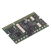
AS-Interface printed circuit board module VAA-4E4A-CB-ZE/E2-Y129640
- Integrated communication monitoring function
- Inputs and outputs short-circuit and overload proof
- Connection via Card-Edge plug connector (AMP 145432-2)
- Power supply of outputs from the external auxiliary voltage
- Inputs are galvanically separated from each other
- Detection of output overload
- Function display for bus, ext. auxiliary voltage, inputs and outputs
- Addressing jack
Please note: All product-related documents, such as certificates, declarations of conformity, etc., which were issued prior to the conversion under the name Pepperl+Fuchs GmbH or Pepperl+Fuchs AG, also apply to Pepperl+Fuchs SE.
Last ned komplett datablad som PDF:
Datablad utdrag: Tekniske data for VAA-4E4A-CB-ZE/E2-Y129640
| Produktbeskrivelse |
|---|
| Circuit board module 4 inputs/4 outputs |
| General specifications | ||
|---|---|---|
| Node type | Standard node | |
| AS-Interface specification | V2.1 | |
| Indicators/operating means | ||
| LED FAULT | error display; LED red red: communication error or address is 0 red flashing: overload of outputs |
|
| LED PWR | AS-Interface voltage; LED green | |
| LED AUX | ext. auxiliary voltage UAUX ; LED green | |
| LED IN | switching state (input); 4 LED yellow | |
| LED OUT | Switching state (output); 4 LED yellow | |
| Electrical specifications | ||
| Auxiliary voltage (input) | 20 ... 30 V DC PELV | |
| Auxiliary voltage (output) | 20 ... 30 V DC PELV | |
| Rated operating voltage | 26.5 ... 31.6 V from AS-Interface | |
| Rated operating current | ≤ 40 mA | |
| Protection class | III | |
| Input | ||
| Number/Type | 4 inputs for 2- or 3-wire sensors (PNP), DC | |
| Supply | from external auxiliary voltage UEXT | |
| Input current | ≤ 8 mA (limited internally) | |
| Switching point | according to EN 61131-2 Type 2 | |
| 0 (unattenuated) | ≤ 2 mA | |
| 1 (attenuated) | ≥ 4 mA | |
| Output | ||
| Number/Type | 4 electronic outputs, PNP | |
| Supply | from external auxiliary voltage UAUX | |
| Current | ≤ 700 mA per output | |
| Standard conformity | ||
| Degree of protection | EN 60529:2000 | |
| AS-Interface | EN 62026-2:2013 | |
| Programming instructions | ||
| Profile | S-7.0 | |
| IO code | 7 | |
| ID code | 0 | |
| ID1 code | F | |
| ID2 code | E | |
| Data bits (function via AS-Interface) | ||
| D0 | ||
| D1 | ||
| D2 | ||
| D3 | ||
| Parameter bits (programmable via AS-i) | function | |
| P0 | not used | |
| P1 | not used | |
| P2 | not used | |
| P3 | not used | |
| Ambient conditions | ||
| Ambient temperature | -25 ... 60 °C (-13 ... 140 °F) | |
| Storage temperature | -25 ... 85 °C (-13 ... 185 °F) | |
| Mechanical specifications | ||
| Connection | Card edge connector, type AMP 145432-2 | |
| Mass | approx. 13 g | |
| Dimensions | 65.7 mm x 40 mm x 8 mm | |
| Width | 40 mm | |
| Length | 65.7 mm | |
Classifications
| System | Classcode |
|---|---|
| ECLASS 13.0 | 27242604 |
| ECLASS 12.0 | 27242604 |
| ECLASS 11.0 | 27242604 |
| ECLASS 10.0.1 | 27242604 |
| ECLASS 9.0 | 27242604 |
| ECLASS 8.0 | 27242604 |
| ECLASS 5.1 | 27242604 |
| ETIM 9.0 | EC001599 |
| ETIM 8.0 | EC001599 |
| ETIM 7.0 | EC001599 |
| ETIM 6.0 | EC001599 |
| ETIM 5.0 | EC001599 |
| UNSPSC 12.1 | 39121535 |
Details: VAA-4E4A-CB-ZE/E2-Y129640
Function
The AS-Interface printed circuit board module is intended for use in backplane applications that offer the possibility of highly flexible configuration with additional plug-in modules.
Mounting and contact are achieved by plugging into a plug-in slot on the backplane side (Card Edge Type AMP 145432-2). Mechanical coding protects the printed circuit board modules against being inserted incorrectly, thus reversing polarity. Mechanical locking in the connector prevents the printed circuit board module from accidentally coming loose after it has been plugged in.
Power must be supplied externally to the inputs and outputs connected to the module through an auxiliary power source. Power is supplied to the module itself from the AS-Interface circuit. This is indicated by an LED.
The inputs are galvanically separated from each other and from the outputs. The current switching state of each input and output is indicated by the corresponding IN and OUT LEDs.
The "periphery error" function as well as the FAULT LED will report an overloading of the outputs to the AS-Interface master. Communication over the AS-Interface remains in effect.
Note:
A communication monitoring system is integrated that deenergises the outputs if no communication is taking place on the AS-Interface line.
Product Documentation: VAA-4E4A-CB-ZE/E2-Y129640
| Brief Instructions | Språk | Filtype | Filstørrelse |
|---|---|---|---|
| Instruction leaflet / Beipackzettel | ALL | 454 KB |
Approvals: VAA-4E4A-CB-ZE/E2-Y129640
| Declaration of Conformity | Sertifikatnummer | Språk | Filtype | Filstørrelse |
|---|---|---|---|---|
| EU Declaration of Conformity (P+F) / EU-Konformitäterklärung (P+F) | DOC-2715B | ALL | 116 KB |
AS-Interface Switch Cabinet Module KE5 – Simple Handling and Improved Manageability

The unique housing design of the new KE5 switch cabinet module enables distinct visibility and simplifies mounting, wiring, and maintenance inside switch cabinets and junction boxes.


 +47 3557 3800