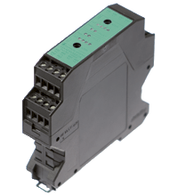
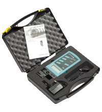
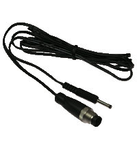
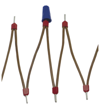
AS-Interface data coupler VAA-4E4A-KE2-DK
- Module for bidirectional data exchange between two AS-Interface circuits
- 2 AS-Interface connections
- 4 inputs/4 outputs per slave (internally connected)
- Housing with removable terminals
- Function display for all outputs
- Communication monitoring
- Addressing via 2 sockets in the front plate
Please note: All product-related documents, such as certificates, declarations of conformity, etc., which were issued prior to the conversion under the name Pepperl+Fuchs GmbH or Pepperl+Fuchs AG, also apply to Pepperl+Fuchs SE.
Last ned komplett datablad som PDF:
Datablad utdrag: Tekniske data for VAA-4E4A-KE2-DK
| Produktbeskrivelse |
|---|
| Control cabinet module Data coupler |
| General specifications | ||
|---|---|---|
| Node type | Standard node | |
| AS-Interface specification | V3.0 | |
| Required gateway specification | ≥ V2.0 | |
| Indicators/operating means | ||
| LED FAULT | error display; LED red red: communication error or address is 0 red flashing: overload of outputs |
|
| LED PWR | AS-Interface voltage; 2 LED green | |
| LED OUT | Switching state (output); 8 LED yellow O10-O13: AS-Interface 1; O20-O23: AS-Interface 2 |
|
| Electrical specifications | ||
| Rated operating voltage | 26.5 ... 31.6 V from AS-Interface | |
| Rated operating current | ≤ 80 mA | |
| Input | ||
| Number/Type | 4 internal inputs per AS-Interface circuit 1+2 | |
| Output | ||
| Number/Type | 4 internal outputs per AS-Interface circuit 1+2 | |
| Directive conformity | ||
| Electromagnetic compatibility | ||
| Directive 2014/30/EU | EN 62026-2:2013 EN 61000-6-2:2005, EN 61000-6-4:2001 | |
| Standard conformity | ||
| Electromagnetic compatibility | EN 61000-6-2:2005, EN 61000-6-4:2001, EN 50295:1999 | |
| Degree of protection | EN 60529:2000 | |
| AS-Interface | EN 62026-2:2013 | |
| Programming instructions | ||
| Profile | S-7.F.F | |
| IO code | 7 | |
| ID code | F | |
| ID1 code | F | |
| ID2 code | E | |
| Data bits (function via AS-Interface) | The output of AS-Interface 1 is the input to AS-Interface 2 The output of AS-Interface 2 is the input to AS-Interface 1 |
|
| D0 | ||
| D1 | ||
| D2 | ||
| D3 | ||
| Parameter bits (programmable via AS-i) | function | |
| P0 | not used | |
| P1 | not used | |
| P2 | not used | |
| P3 | not used | |
| Ambient conditions | ||
| Ambient temperature | 0 ... 55 °C (32 ... 131 °F) | |
| Storage temperature | -25 ... 85 °C (-13 ... 185 °F) | |
| Mechanical specifications | ||
| Degree of protection | IP20 | |
| Connection | removable terminals, terminal connection ≤ 2.5 mm2 | |
| Material | ||
| Housing | PA 66-FR | |
| Mass | 130 g | |
| Dimensions | ||
| Height | 85 mm | |
| Width | 22.5 mm | |
| Length | 99 mm | |
| Mounting | DIN mounting rail | |
Classifications
| System | Classcode |
|---|---|
| ECLASS 13.0 | 27242604 |
| ECLASS 12.0 | 27242604 |
| ECLASS 11.0 | 27242604 |
| ECLASS 10.0.1 | 27242604 |
| ECLASS 9.0 | 27242604 |
| ECLASS 8.0 | 27242604 |
| ECLASS 5.1 | 27242604 |
| ETIM 9.0 | EC001599 |
| ETIM 8.0 | EC001599 |
| ETIM 7.0 | EC001599 |
| ETIM 6.0 | EC001599 |
| ETIM 5.0 | EC001599 |
| UNSPSC 12.1 | 39121535 |
Details: VAA-4E4A-KE2-DK
Function
The data coupler module VAA-4E4A-KE2-DK is used to exchange data via two AS-Interface circuits. The data coupler itself consists of two 4E4A slaves in a single housing. The output bits of the AS-Interface circuit 1 are represented at the AS-Interface circuit 2 as input bits, and vice versa. This permits a bidirectional data exchange without the need to transfer the data via an overriding control. This is a particular advantage in time-critical applications. The addressing of both integrated AS-Interface slaves is mutually independent. Two addressing jacks are available on the front panel.
By using two independent AS-Interface connections the related inputs and outputs are electrically separated. This prevents problems with potential shifting (mass potential).
For status indication each slave has 6 LEDs on the front panel, 4 LEDs for the 4 outputs, 1 LED for the voltage indication, and 1 LED for indicating AS-Interface error messages.
The housing of only 22.5 mm width requires little room in the switch cabinet. The module is installed by snapping it onto the 35 mm mounting rail in accordance with EN 50022.
Connections are made via pluggable screw terminals. This enables the easy disconnection during commissioning or service.
Product Documentation: VAA-4E4A-KE2-DK
| Brief Instructions | Språk | Filtype | Filstørrelse |
|---|---|---|---|
| Instruction leaflet / Beipackzettel | ALL | 453 KB |
Design / Simulation: VAA-4E4A-KE2-DK
| CAD | Språk | Filtype | Filstørrelse |
|---|---|---|---|
| CAD 3-D / CAD 3-D | ALL | STP | 1664 KB |
| CAD Portal / CAD Portal | ALL | LINK | --- |
Approvals: VAA-4E4A-KE2-DK
| Declaration of Conformity | Sertifikatnummer | Språk | Filtype | Filstørrelse |
|---|---|---|---|---|
| EU Declaration of Conformity (P+F) / EU-Konformitäterklärung (P+F) | DOC-2454C | ALL | 109 KB |
Relaterte produkter: VAA-4E4A-KE2-DK
| Accessories | ||||||
|---|---|---|---|---|---|---|
|
||||||
|
||||||
|
||||||
AS-Interface Switch Cabinet Module KE5 – Simple Handling and Improved Manageability

The unique housing design of the new KE5 switch cabinet module enables distinct visibility and simplifies mounting, wiring, and maintenance inside switch cabinets and junction boxes.


 +47 3557 3800