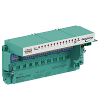
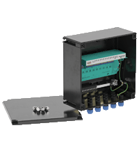
Multi-Input/Output R8D0-MIO-Ex12.FF*
- For discrete inputs and outputs
- Installation in Zone 1/Div. 1, intrinsically safe
- Sensors in Zone 0/Div. 1
- Connection to fieldbus acc. to FISCO or Entity
- For FOUNDATION Fieldbus H1
- PCS integration via device description and function blocks
- Monitors sensor condition
- Removable terminals
- Power, Com, Diagnostics, and Error LEDs
- Test points for easy troubleshooting
Please note: All product-related documents, such as certificates, declarations of conformity, etc., which were issued prior to the conversion under the name Pepperl+Fuchs GmbH or Pepperl+Fuchs AG, also apply to Pepperl+Fuchs SE.
Last ned komplett datablad som PDF:
Datablad utdrag: Tekniske data for R8D0-MIO-Ex12.FF*
| Produktbeskrivelse |
|---|
| Multi-input/output for digital signals, module for DIN rail mounting |
| General specifications | ||
|---|---|---|
| Design / Mounting | Cabinet installation | |
| Installation in hazardous area | Zone 1 / Div. 1 | |
| Fieldbus connection | ||
| Fieldbus type | FOUNDATION Fieldbus | |
| Physical layer profile | profile type 511 (FISCO), profile type 111 (Entity) | |
| ITK version | 6.1.1 | |
| Implementation | resource block 1x RS function block 4x DO, 12x DI, 1x AI, 2x MDI, 1x MDO transducer block 4x TB |
|
| FDE (Fault Disconnect Equipment) | 6.7 mA | |
| Polarity | not polarity sensitive | |
| Rated voltage | 9 ... 32 V | |
| Rated current | max. 23 mA | |
| Indicators/operating means | ||
| LED PWR | green: on, bus voltage existent | |
| LED COM ERR | red, continuous lightning: hardware error; red, flashing: no bus activities or bus fault; off: no error | |
| LED CHANNEL ERROR | red, flashing: lead breakage/short circuit; off: no error | |
| DIP switch | Address setting , write protection , simulation | |
| Analog input | ||
| Number of inputs | 1 | |
| Input type | Frequency input / Counter Input , channel 1 | |
| Accuracy | 0.5 % of the measured value | |
| Switching frequency | min. 0.1 Hz max. 5 kHz | |
| Pulse duration | min. 80 µs | |
| Supply voltage | 5 V | |
| Supply current | 5 mA | |
| Line fault detection | lead breakage , short circuit (not in counter mode) | |
| Digital input | ||
| Number of inputs | 12 | |
| Input type | Sensor input , channels 1, 4, 7, 10 multiplexed , cycle adjustable | |
| Supply voltage | 6.6 V | |
| Supply current | 5 mA | |
| Line fault detection | lead breakage , short circuit | |
| Input type | Sensor input , channels 2, 3, 5, 6, 8, 9, 11, 12 multiplexed , cycle fixed | |
| Supply voltage | 5 V | |
| Supply current | 5 mA | |
| Time delay before availability | 2 ms | |
| Line fault detection | lead breakage , short circuit | |
| Digital output | ||
| Number of outputs | 4 | |
| Output type | Low power valve , channels 1, 4, 7, 10 | |
| Supply voltage | 6.6 V | |
| Supply current | 1.5 mA | |
| Line fault detection | lead breakage , short circuit | |
| Galvanic isolation | ||
| Foundation Fieldbus/Field circuit | safe galvanic isolation acc. to EN 60079-11, voltage peak value 375 V | |
| Directive conformity | ||
| Electromagnetic compatibility | ||
| Directive 2014/30/EU | EN 61326-1:2013 | |
| Low voltage | ||
| Directive 2014/35/EU | EN 61010-1:2010 | |
| Standard conformity | ||
| Galvanic isolation | EN 60079-11 | |
| Electromagnetic compatibility | NE 21:2011 | |
| Degree of protection | IEC/EN 60529 | |
| Fieldbus standard | IEC 61158-2 | |
| Shock resistance | EN 60068-2-27 | |
| Vibration resistance | EN 60068-2-6 | |
| Ambient conditions | ||
| Ambient temperature | -50 ... 75 °C (-58 ... 167 °F) hazardous area -50 ... 85 °C (-58 ... 185 °F) safe area |
|
| Storage temperature | -40 ... 85 °C (-40 ... 185 °F) | |
| Relative humidity | ≤ 95 % non-condensing | |
| Shock resistance | 15 g , 11 ms | |
| Vibration resistance | 5 g , 10 ... 150 Hz | |
| Pollution degree | 2 | |
| Corrosion resistance | acc. to ISA-S71.04-1985, severity level G3 | |
| Mechanical specifications | ||
| Connection type | plug-in terminals , spring terminal and screw terminal | |
| Core cross section | ||
| Bus | up to 2.5 mm2 | |
| Inputs | up to 2.5 mm2 | |
| Housing material | Polycarbonate | |
| Degree of protection | IP20 | |
| Mass | approx. 290 g | |
| Mounting | DIN rail mounting | |
| Data for application in connection with hazardous areas | ||
| EU-type examination certificate | BVS 16 ATEX E 075 X | |
| Marking |  II 2 (1) G Ex ib [ia Ga] IIC T4 Gb , II 2 (1) G Ex ib [ia Ga] IIC T4 Gb ,  II 3 (1) G Ex ic [ia Ga] IIC T4 Gc , II 3 (1) G Ex ic [ia Ga] IIC T4 Gc ,  II 3 (1) G Ex ec [ia Ga] IIC T4 Gc , II 3 (1) G Ex ec [ia Ga] IIC T4 Gc ,  I (M1) [Ex ia Ma] I , I (M1) [Ex ia Ma] I ,  II (1) D [Ex ia Da] IIIC II (1) D [Ex ia Da] IIIC |
|
| Field-side | ||
| Voltage | 9 V | |
| Current | 43 mA | |
| Power | 96 mW | |
| FOUNDATION Fieldbus | ||
| Maximum safe voltage | 253 V | |
| Voltage | 24 V | |
| Current | 380 mA | |
| Power | 5.32 W | |
| Directive conformity | ||
| Directive 2014/34/EU | EN 60079-0:2012 , EN 60079-11:2012 , EN 60079-7:2015 | |
| International approvals | ||
| FM approval | pending | |
| IECEx approval | IECEx BVS 16.0051X | |
| Approved for | Ex ib [ia Ga] IIC T4 Gb , Ex ic [ia Ga] IIC T4 Gc , Ex ec [ia Ga] IIC T4 Gc , [Ex ia Da] IIIC , [Ex ia Ma] I |
|
| Certificates and approvals | ||
| Marine approval | pending | |
| General information | ||
| Supplementary information | EC-Type Examination Certificate, Statement of Conformity, Declaration of Conformity, Attestation of Conformity and instructions have to be observed where applicable. For information see www.pepperl-fuchs.com. | |
Classifications
| System | Classcode |
|---|---|
| ECLASS 13.0 | 27242610 |
| ECLASS 12.0 | 27242610 |
| ECLASS 11.0 | 27242610 |
| ECLASS 10.0.1 | 27242610 |
| ECLASS 9.0 | 27242610 |
| ECLASS 8.0 | 27242610 |
| ECLASS 5.1 | 27242610 |
| ETIM 9.0 | EC001601 |
| ETIM 8.0 | EC001601 |
| ETIM 7.0 | EC001601 |
| ETIM 6.0 | EC001601 |
| ETIM 5.0 | EC001604 |
| UNSPSC 12.1 | 39121008 |
Details: R8D0-MIO-Ex12.FF*
Function
The multi-input/output (MIO) is a multifunctional device for DIN rail installation and connects discrete inputs and outputs to fieldbus. It is typically installed in a field enclosure close to the sensors in the hazardous area, thereby minimizing wiring. The MIO is certified intrinsically safe and as associated apparatus: inputs and outputs are intrinsically safe even when the fieldbus connection is not.
The MIO device provides connections for up to 12 discrete inputs and 4 discrete outputs. The device is compatible to components FD0-VC-Ex* and FD0-BI-* and offers control and position feedback for 4 low-power valves. Measurements for breakaway time and runtime can be set with limits for alarming. Automatic partial stroke testing is configurable. 4 inputs can be configured for vibrating forks and 1 input for frequency and counter signals, e. g., for rotating equipment.
The MIO communicates data, configuration, alarms and function blocks to the distributed control system (DCS). The fieldbus powers the sensors and the MIO itself, extra power or wiring are not required.
Informative Literature: R8D0-MIO-Ex12.FF*
| Literature | Språk | Filtype | Filstørrelse |
|---|---|---|---|
| Application Report - Controlling and Monitoring liquid Helium at the Deutsches Elektronen-Synchrotron | ENG | 361 KB | |
| Application Report - Digital Communication in Steel-Plate Manufacturing | ENG | 470 KB |
Product Documentation: R8D0-MIO-Ex12.FF*
| System Descriptions | Språk | Filtype | Filstørrelse |
|---|---|---|---|
| Planning and integration: Compatibility list of sensors and pilot valves | ENG | 50 KB | |
| Safety and Security Documentation | |||
| Instruction manual | ENG | 174 KB | |
| Manuals | |||
| Manual | ENG | 1595 KB | |
Design / Simulation: R8D0-MIO-Ex12.FF*
| CAD | Språk | Filtype | Filstørrelse |
|---|---|---|---|
| CAD-files 2-D / CAD-Dateien 2-D | ALL | ZIP | 854 KB |
Approvals: R8D0-MIO-Ex12.FF*
| Certificates | Sertifikatnummer | Språk | Filtype | Filstørrelse |
|---|---|---|---|---|
| Brasil TUV Rheinland Brazil | TÜV 17.2298 X | ALL | 1257 KB | |
| Canada FM | FM19CA0042X | ALL | 1698 KB | |
| China SITIIAS CCC Ex Certificate | 2021322314004067 (Singapore) | ALL | 1616 KB | |
| Europe ATEX | BVS 16 ATEX E 075 X | ALL | 1629 KB | |
| IECEx Certificate of Conformity | IECEx BVS 16.0051X | ALL | LINK | --- |
| USA FM | FM19US0077X | ALL | 1700 KB | |
| Worldwide Fieldbus Foundation | IT110300/02 | ALL | 115 KB | |
| Declaration of Conformity | ||||
| EU Declaration of Conformity (P+F) / EU-Konformitäterklärung (P+F) | DOC-3160D | ALL | 1064 KB | |
Software: R8D0-MIO-Ex12.FF*
| Device Description Files/Drivers | Frigivelsesinfo | Filtype | Filstørrelse |
|---|---|---|---|
| DD/CFF files / DD/CFF-Dateien | 0104/010102 | ZIP | 209 KB |
Relaterte produkter: R8D0-MIO-Ex12.FF*
| Variants | ||||||
|---|---|---|---|---|---|---|
|
||||||
|
||||||
| Matching System Components | ||||||
|
||||||
RSS Info Service for PANOS Updates

Stay informed when a new software update of PANOS, the operating system for Ethernet-APL switches, is released: With our RSS Feed you will get an email notfication in your inbox immediately after an update has been released.


 +47 3557 3800