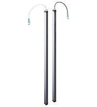
Light grid LGM50
- Measuring automation light grid with switching output
- Optical resolution 50 mm
- Super-fast object detection, even with 3-way beam crossover
- Object identification using integrated object recognition
- IO-Link interface for service and process data
- Temperature range to -30 °C
- Output of a measured value, can be selected from a number of measuring functions
Please note: All product-related documents, such as certificates, declarations of conformity, etc., which were issued prior to the conversion under the name Pepperl+Fuchs GmbH or Pepperl+Fuchs AG, also apply to Pepperl+Fuchs SE.
Last ned komplett datablad som PDF:
Datablad utdrag: Tekniske data for LGM50
| Produktbeskrivelse |
|---|
| Measuring automation light grid with beam spacing of 50 mm, IO-Link interface, push-pull output, fixed cable with M12 plug |
| General specifications | ||
|---|---|---|
| Effective detection range | Standard : 0.3 ... 6 m | |
| Threshold detection range | 7.5 m | |
| Light source | IRED | |
| Light type | modulated infrared light , 850 nm | |
| Field height | see Table 1, max. 3000 mm | |
| Beam crossover | Factory setting: three beam crossing, deactivateable | |
| Beam blanking | adjustable max. 2 fixed suppressible beam areas (blanking) | |
| Beam spacing | 50 mm | |
| Number of beams | see Table 1, max. 61 | |
| Operating mode | Emitter: Emitter power adjustable in two ranges | |
| Optical resolution | without beam crossover: 50 mm with beam crossover: 25 mm with in 25% and 75% of the range |
|
| Opening angle | 10 ° | |
| Ambient light limit | > 50000 Lux (if external light source is outside the opening angle) | |
| Functional safety related parameters | ||
| MTTFd | 56 a | |
| Mission Time (TM) | 20 a | |
| Diagnostic Coverage (DC) | 60 % | |
| Indicators/operating means | ||
| Operation indicator | LED green: constantly on - power-on double pulse flashing (0.8 Hz) - undervoltage flashing (4 Hz) - short circuit flashing with short break (1 Hz) - IO-Link mode |
|
| Status indicator | Emitter: LED yellow constantly on - high emitter power constantly off - low emitter power flashing (8 Hz) - error message Receiver: LED yellow: constantly on - object detected constantly off - no object detected flashing (4 Hz) - falling below operating reserve flashing (8 Hz) - error message |
|
| Control elements | Receiver: 2 touch buttons for programming | |
| Electrical specifications | ||
| Operating voltage | 18 ... 30 V DC | |
| Ripple | 10 % | |
| No-load supply current | Emitter ≤: 50 mA Receiver: ≤ 150 mA (without outputs) |
|
| Time delay before availability | see Table 1, max. 1.5 s | |
| Interface | ||
| Interface type | IO-Link ( pin 4 ) | |
| IO-Link revision | 1.0 | |
| Device ID | 1050371 ... 1050398 ( 0x100703 ... 0x10071E ) | |
| COM-Mode | COM2 (38.4 kBit/s) | |
| Min. cycle time | 2.3 ms | |
| Process data width | 16 bit | |
| SIO mode support | yes | |
| Input | ||
| Test input | Emitter switch-off with +UB or 0 V at pin 4 (emitter) | |
| Function input | Range input activation from 1.6 m with +UB or 0 V on pin 2 (emitter) Teach-In input for parameterization on pin 8 (receiver) |
|
| Output | ||
| Stability alarm output | Stability Control (SC) 1 PNP, short-circuit protected, reverse polarity protected on pin 2 (receiver) | |
| Switching type | Factory setting: dark on , Switchable to light-on mode | |
| Signal output | Command interface: Pin 4 IO-Link interface C or used as switching output Q; 1 short-circuit proof reverse polarity protected push-pull output (receiver) Switch output: Pin 5 switching output Q; 1 short-circuit proof reverse polarity protected push-pull output (receiver) synchronized with pin 4 |
|
| Switching threshold | Factory setting: The signal tracking for the threshold value is deactivated, increasing the optical resolution by a maximum of 4 mm; switchable to active signal tracking | |
| Switching voltage | max. 30 V DC | |
| Switching current | max. 100 mA | |
| Voltage drop | ≤ 2 V DC | |
| Switching frequency | see Table 1, max. 129 Hz | |
| Response time | see Table 1, max. 8 ms | |
| Timer function | Off-delay programmable from 0 ... 1.25 s in 5 ms steps (adjustment via IO-Link only) | |
| Conformity | ||
| Communication interface | IEC 61131-9 | |
| Product standard | EN 60947-5-2 | |
| Approvals and certificates | ||
| Protection class | III ( IEC 61140 ) | |
| UL approval | cULus Listed | |
| CCC approval | CCC approval / marking not required for products rated ≤36 V | |
| Ambient conditions | ||
| Ambient temperature | -30 ... 60 °C (-22 ... 140 °F) | |
| Storage temperature | -30 ... 70 °C (-22 ... 158 °F) | |
| Mechanical specifications | ||
| Conductor cross section | min. 0.25 mm2 | |
| Housing length L | see Table 1, max. 3160 mm | |
| Degree of protection | IP67 | |
| Connection | Emitter: connecting cable with 4-pin, M12 x 1 connector , 330 mm total length Receiver: connecting cable with 8-pin, M12 x 1 connector , 350 mm total length |
|
| Material | ||
| Housing | extruded aluminum section , Silver anodized | |
| Optical face | Plastic pane , Polycarbonate | |
| Mass | see Table 1, max. 1650 g (per profile) | |
| Dimensions | ||
| Width | 20 mm | |
| Depth | 30.5 mm | |
| Cable length | max. 30 m | |
Classifications
| System | Classcode |
|---|---|
| ECLASS 13.0 | 27270910 |
| ECLASS 12.0 | 27270910 |
| ECLASS 11.0 | 27270910 |
| ECLASS 10.0.1 | 27270910 |
| ECLASS 9.0 | 27270910 |
| ECLASS 8.0 | 27270910 |
| ECLASS 5.1 | 27270910 |
| ETIM 9.0 | EC002549 |
| ETIM 8.0 | EC002549 |
| ETIM 7.0 | EC002549 |
| ETIM 6.0 | EC002549 |
| ETIM 5.0 | EC002549 |
| UNSPSC 12.1 | 39121528 |
Details: LGM50
Function
Automation light grids in the LGM Series are designed to measure small to large objects. The slimline light grids are modular in design and are available with various beam gaps and field heights. The entire signal evaluation process is carried out within the device. The lightweight systems can be integrated elegantly into their surroundings, from both a technical and a visual perspective. As a result, machines and plants operating in temperature ranges between -30 °C ... +60 °C can be designed to more compact dimensions.
Informative Literature: LGM50
| Literature | Språk | Filtype | Filstørrelse |
|---|---|---|---|
| Brochure - Automation Light Grids: LGS and LGM Series | ENG | 1965 KB |
Product Documentation: LGM50
| Product information | Språk | Filtype | Filstørrelse |
|---|---|---|---|
| Installation and user instructions for offline parameterization of IO-Link sensors | ENG | 1788 KB | |
| Brief Instructions | |||
| Brief Instructions - LGM series | ENG | 1759 KB | |
| Manuals | |||
| Manual Measuring Automation Light Grid LGM | ENG | 6975 KB | |
Design / Simulation: LGM50
| CAD | Språk | Filtype | Filstørrelse |
|---|---|---|---|
| 3-D model, 1200 mm / 3-D-Modell, 1200 mm | ALL | STP | 1815 KB |
| 3-D model, 1500 mm / 3-D-Modell, 1500 mm | ALL | STP | 1788 KB |
| 3-D model, 1800 mm / 3-D-Modell, 1800 mm | ALL | STP | 1771 KB |
| 3-D model, 2100 mm / 3-D-Modell, 2100 mm | ALL | STP | 1769 KB |
| 3-D model, 2400 mm / 3-D-Modell, 2400 mm | ALL | STP | 1760 KB |
| 3-D model, 2700 mm / 3-D-Modell, 2700 mm | ALL | STP | 1756 KB |
| 3-D model, 300 mm / 3-D-Modell, 300 mm | ALL | STP | 1787 KB |
| 3-D model, 3000 mm / 3-D-Modell, 3000 mm | ALL | STP | 1755 KB |
| 3-D model, 600 mm / 3-D-Modell, 600 mm | ALL | STP | 1781 KB |
| 3-D model, 900 mm / 3-D-Modell, 900 mm | ALL | STP | 1791 KB |
| CAD Portal / CAD Portal | ALL | LINK | --- |
Approvals: LGM50
| Certificates | Sertifikatnummer | Språk | Filtype | Filstørrelse |
|---|---|---|---|---|
| Canada USA UL Ordinary Location | E87056 | ALL | LINK | --- |
| Canada USA UL Ordinary Location | UL-CA-2134531-0 / UL-US-2141152-0 | ALL | 544 KB | |
| IO-Link Manufacturer Declaration | PF 13 CERT 2915 | ALL | 36 KB | |
| Declaration of Conformity | ||||
| EU Declaration of Conformity (P+F) / EU-Konformitäterklärung (P+F) | DOC-0227B | ALL | 184 KB | |
| EU Declaration of Conformity (P+F) / EU-Konformitäterklärung (P+F) | DOC-0227C | ALL | 304 KB | |
| UK Declaration of Conformity (P+F) / UK-Konformitäterklärung (P+F) | DOC-5336 | ALL | 228 KB | |
Software: LGM50
| Device Description Files/Drivers | Frigivelsesinfo | Filtype | Filstørrelse |
|---|---|---|---|
| IODD for LGM series / IODD für LGM Serie | V1.01.000 / 2018-08-15 | ZIP | 2631 KB |
| Device DTM for LGM IO-Link sensors / Geräte-DTM für LGM IO-Link Sensoren | V1.0.2.5 | ZIP | 3905 KB |
| Software Tools | |||
| IO-Link Offline Parameterization Tool / IO-Link Offline-Parametriertool | V1.00.006 / 2022-07-10 | ZIP | 96138 KB |
Relaterte produkter: LGM50
| Accessories | ||||||
|---|---|---|---|---|---|---|
|
||||||
|
||||||
|
||||||
|
||||||
|
||||||
|
||||||
|
||||||
|
||||||
|
||||||
|
||||||
|
||||||
|
||||||
|
||||||
|
||||||
|
||||||
|
||||||
|
||||||
|
||||||
|
||||||
|
||||||
|
||||||
|
||||||
|
||||||
|
||||||
|
||||||
|
||||||
|
||||||






 +47 3557 3800