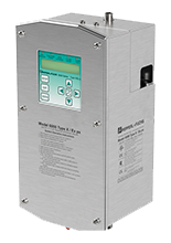
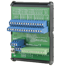
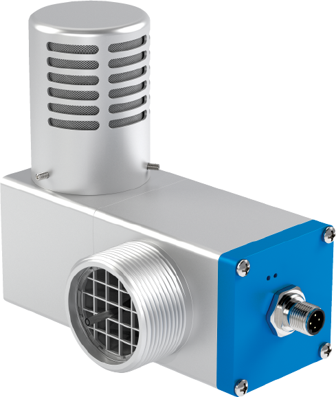
Type X and Ex pxb purge and pressurization control unit 6000 Control System
- Certified for Class I, Class II, Division I; Zone 1 / Zone 21 to nonhazardous
- Intrinsically safe electrical/pneumatic manifold assembly
- Intrinsically safe user interface for programming and monitoring the system
- Enclosure volume up to 450 ft3 (12.7 m3)
- Control Unit monitors system operation and controls enclosure power
- Universal mounting (brackets included)
- 316L stainless steel Type 4X enclosure
Please note: All product-related documents, such as certificates, declarations of conformity, etc., which were issued prior to the conversion under the name Pepperl+Fuchs GmbH or Pepperl+Fuchs AG, also apply to Pepperl+Fuchs SE.
Last ned komplett datablad som PDF:
Datablad utdrag: Tekniske data for 6000 Control System
| Produktbeskrivelse |
|---|
| 6000 Series Type X and Ex pxb purge and pressurization system control unit |
| General specifications | ||
|---|---|---|
| Operating mode | manual, semi-automatic, or fully automatic - programmable | |
| Series | 6000 Series | |
| System | Type X Purge ; Ex pxb Purge | |
| Number of volume exchanges | 4 to 19 | |
| Hazardous environment | gas, dust, gas and dust | |
| Supply | ||
| Rated voltage | 90 ... 264 V AC, 48 ... 62 Hz / 0.2 A 20 ... 30 V DC |
|
| Electrical specifications | ||
| Connection | Terminal blocks | |
| Input | ||
| Input I | Inputs 1, 2, 3, 4: contact input, 5 VDC @ 2 mA | |
| Input type | intrinsically safe | |
| Input II | Temperature inputs | |
| Input type | intrinsically safe | |
| Sensor type | 6000-TEMP | |
| Input III | EPV-6000 Vent | |
| Input type | intrinsically safe | |
| Input IV | User interface module | |
| Connection | M8 connector, 4-pin | |
| Input type | intrinsically safe | |
| Output | ||
| Output I | AUX 1 | |
| Output type | Dry contacts, SPDT | |
| Inrush current | 5 A | |
| Contact loading | 2 A @ 240 VAC resistive load 2 A @ 24 VDC |
|
| Output II | AUX 2 | |
| Output type | Dry contacts, SPDT | |
| Inrush current | 5 A | |
| Contact loading | 2 A @ 240 VAC resistive load 2 A @ 24 VDC |
|
| Output III | ENC_1, ENC_2 (protected enclosure contacts) | |
| Output type | Dry contacts (2) SPST, NO | |
| Contact loading | 8 A @ 240 VAC / 120 VAC resistive load 8 A @ 24 VDC |
|
| Indicators/settings | ||
| LED indication | Safe pressure: Blue - safe pressure is achieved Enclosure power: Green - power on; Red - power off Rapid exchange: Blue - purging is running System bypass: Yellow - bypass is activated Alarm fault: Red (blinking) - any alarm input detected; Red (solid) - 6000 series system fault |
|
| Pneumatic parameters | ||
| Protective gas supply | instrument grade air or inert gas | |
| Pressure requirement | 20 ... 120 psig (1.4 ... 8.3 bar) (138 ... 827 kPa) regulated | |
| Safe pressure | Gas: 0.25" wc (6.4 mm wc) (0.625 mbar) (62 Pa) Dust: 0.65" wc (16.5 mm wc) (1.6 mbar) (162 Pa) Gas and Dust: 0.65" wc (16.5 mm wc) (1.6 mbar) ( 162 Pa) |
|
| Purge flow rate | Maximum flow rate measurement for enclosure size (enclosure volume:flow rate): < 20 ft3 (0.57 m3): 5, 12 SCFM (141, 340 l/min), or dynamic 20 ... 30 ft3 (0.57 ... 0.85 m3): 5, 12, 20 SCFM (141, 340, 565 l/min), or dynamic > 30 ft3 (0.85 m3): 5, 12, 20, 30 SCFM (141, 340, 565, 850 l/min), or dynamic |
|
| Purge flow and enclosure pressure rate | With EPV-6000-xx-01, EPV-6000-xx-02 5 SCFM @ 1.5" wc, (141 l/min @ 3.7 mbar) 12 SCFM @ 2.0" wc, (340 l/min @ 5.0 mbar) 20 SCFM @ 2.7" wc, (565 l/min @ 6.7 mbar) 30 SCFM @ 4.1" wc, (850 l/min @ 10.2 mbar) With EPV-6000-xx-03, EPV-6000-xx-04 5 SCFM @ 2.1" wc, (141 l/min @ 5.2 mbar) 12 SCFM @ 2.6" wc, (340 l/min @ 6.5 mbar) 20 SCFM @ 4.1" wc, (565 l/min @ 10.2 mbar) 30 SCFM @ 5.3" wc, (850 l/min @ 13.2 mbar) With EPV-6000-xx-05, 06 5 SCFM @ 1.8" wc, (141 l/min @ 4.5 mbar) 12 SCFM @ 2.9" wc, (340 l/min @ 7.3 mbar) 20 SCFM @ 7.4" wc, (565 l/min @ 18.5 mbar) |
|
| Flow rate for leakage compensation | Depends on enclosure seal. With EPV-6000-xx-01, EPV-6000-xx-02 0.35 SCFM @ 0.25" wc (10.0 l/min @ 6.3 mbar) 1.0 SCFM @ 0.75" wc (28.0 l/min @ 1.9 mbar) With EPV-6000-xx-03, EPV-6000-xx-04 0.22 SCFM @ 0.25" wc (6.2 l/min @ 6.3 mbar) 0.58 SCFM @ 0.75" wc (16.4 l/min @ 1.9 mbar) With EPV-6000-xx-05, EPV-6000-xx-06 0.15 SCFM @ 0.25" wc (4.2 l/min @ 6.3 mbar) 0.35 SCFM @ 0.75" wc (10.0 l/min @ 1.9 mbar) |
|
| Ambient conditions | ||
| Ambient temperature | -20 ... 60 °C (-4 ... 140 °F) | |
| Storage temperature | -30 ... 80 °C (-22 ... 176 °F) | |
| Relative humidity | 5 ... 95 %, noncondensing | |
| Vibration resistance | 5 ... 100 Hz , 1 g, 12 m/s2, all axes | |
| Impact resistance | 30 g, 11 ms, all axes | |
| Mechanical specifications | ||
| Connection type | Pneumatic : Inlet fitting to manifold: 3/8" ferrule fitting Outlet fitting from manifold: 3/8" ferrule fitting Inlet fitting to enclosure: 3/8" bulkhead fitting |
|
| Cable gland | 4 - M16 x 1.5 cable gland | |
| Degree of protection | Type 4X , IP66 | |
| Material | Enclosure: 316L (UNS S31603) stainless steel Manifold valve: anodized 6082 aluminum Fittings: 316L (UNS S31603) stainless steel |
|
| Mass | -WH- 11.4 kg (25 lb) -CK- 7.2 kg (16 lb) |
|
| Dimensions | 183 x 367.5 x 152.5 mm (7.20 x 14.45 x 6.00 inch) | |
| Height | 367.5 mm | |
| Width | 183 mm | |
| Depth | 152.5 mm | |
| Data for application in connection with hazardous areas | ||
| EU-type examination certificate | ||
| Marking | 6000 main control unit with housing 6000-xx-S2-UN-xx-xx: ATEX UL/Demko 07 ATEX 0705753X II 2 G Ex db ib [ib Gb] [pxb Gb] IIC T4 Gb (-20 °C ≤ Ta ≤ 60 °C) II 2 D Ex ib tb [ib Db] [pxb Db] IIIC T60°C Db (-20 °C ≤ Ta ≤ 50 °C) 6000 main control unit kit version 6000-xx-S2-UN-CK-xx: ATEX UL/Demko 07 ATEX 0705753X II 2 G Ex db [ib Gb] [pxb Gb] IIC T4 Gb (-20 °C ≤ Ta ≤ 60 °C) II 2 D Ex tb [ib Db] [pxb Db] IIIC T80°C Db (-20 °C ≤ Ta ≤ 60 °C) User interface 6000-UIC-xx: ATEX UL/Demko 07 ATEX 0705753X II 2 G Ex ib [pxb Gb] IIC T4 Gb |
|
| Directive conformity | ||
| Directive 2014/34/EU | IEC/EN 60079-0 IEC/EN 60079-1 IEC/EN 60079-2 IEC/EN 60079-11 IEC/EN 60079-31 |
|
| Directive 94/9/EC | ||
| International approvals | ||
| UL approval | 6000 Main control unit with housing 6000-xx-S2-UN-xx-xx: cULus Class I, Division 1, Groups A,B,C,D T4 (-20 °C ≤ Ta ≤ 60 °C) Class II, Division 1, Groups E,F,G T4 (-20 °C ≤ Ta ≤ 50 °C) Class I, Zone 1, Group IIC T4 (-20 °C ≤ Ta ≤ 60 °C) Class II, Zone 21, Group IIIC T60 °C (-20 °C ≤ Ta ≤ 50 °C) [Ex i] Associated Equipment Ex db ib [ib Gb] [pxb Gb] IIC T4 (-20 °C ≤ Ta ≤ 60 °C) Ex ib tb [ib Db] [pxb Db] IIIC T4 (-20 °C ≤ Ta ≤ 50 °C) 6000 Main control unit kit version 6000-xx-S2-UN-CK-xx: cULus Class I, Division 1, Groups A,B,C,D T4 (-20 °C ≤ Ta ≤ 60 °C) Class II, Division 1, Groups E,F,G T4 (-20 °C ≤ Ta ≤ 60 °C) Class I, Zone 1, Group IIC T4 Class II, Zone 21, Group IIIC T60 °C [Ex i] Associated Equipment Ex db [ib Gb] [pxb Gb] IIC T4 X (-20 °C ≤ Ta ≤ 60 °C) Ex tb [ib Db] [pxb Db] IIIC T4 X (-20 °C ≤ Ta ≤ 60 °C) User interface 6000-UIC-xx: cULus (-20 °C ≤ Ta ≤ 60 °C) Class I, Division 1, Groups A,B,C,D T4 Class I, Zone 1, Group IIC T4 Ex i Intrinsically safe |
|
| IECEx approval | 6000 Main Control unit with housing 6000-xx-S2-UN-xx-xx: IECEx UL 08.0003X Ex db ib [ib Gb] [pxb Gb] IIC T4 Gb (-20 °C ≤ Ta ≤ 60 °C) Ex ib tb [ib Db] [pxb Db] IIIC T60 °C Db (-20 °C ≤ Ta ≤ 50 °C) 6000 Main control unit kit version 6000-xx-S2-UN-CK-xx: IECEx UL 08.0003X Ex db [ib Gb] [pxb Gb] IIC T4 Gb (-20 °C ≤ Ta ≤ 60 °C) Ex tb [ib Db] [pxb Db] IIIC T80 °C Db (-20 °C ≤ Ta ≤ 60 °C) User interface 6000-UIC-xx: IECEx UL 08.0003X Ex ib [pxb Gb] IIC T4 Gb |
|
| General information | ||
| Supplementary information | EC-Type Examination Certificate, Statement of Conformity, Declaration of Conformity, Attestation of Conformity and instructions have to be observed where applicable. For information see www.pepperl-fuchs.com. | |
Classifications
| System | Classcode |
|---|---|
| ECLASS 13.0 | 27180508 |
| ECLASS 12.0 | 27180508 |
| ECLASS 11.0 | 27180508 |
| ECLASS 10.0.1 | 27180508 |
| ECLASS 9.0 | 27180508 |
| ECLASS 8.0 | 27180508 |
| ECLASS 5.1 | 40050501 |
| ETIM 9.0 | EC000243 |
| ETIM 8.0 | EC000243 |
| ETIM 7.0 | EC000243 |
| ETIM 6.0 | EC000243 |
| ETIM 5.0 | EC000243 |
| UNSPSC 12.1 | 39121301 |
Details: 6000 Control System
Function
The 6000 series consists of the control unit (EPCU)and user interface(UIC) mounted in a 316L stainless steel Type 4X (IP66) enclosure with the pneumatic solenoid valve mounted on the unit. The EPV-6000 relief vent is separate and is mounted to the enclosure.
The user interface allows programming of up to 4 switch inputs, temperature modules, enclosure power contacts, 2 auxiliary outputs, and various operational functions. Also, the user interface screen allows monitoring and easy configuration.
Among the additional features are inputs for system bypass, enclosure power on/off, temperature overload and activation of Rapid Exchange flow for cooling or auxiliary relay for separate cooling source, and delay power shutdown.
Component kits are available for custom installations.
Informative Literature: 6000 Control System
| We are sorry, there are no documents for your language selection. Please select another language. |
Product Documentation: 6000 Control System
| Product information | Språk | Filtype | Filstørrelse |
|---|---|---|---|
| Basic Explosion Protection Compendium - Type of Protection "Purge and Pressurization" | ENG | 3860 KB | |
| Brief Instructions | |||
| Programming Tree 6000 Series Purge/Pressurization System | ENG | 1157 KB | |
| Programming Worksheet 6000 Series Purge/Pressurization System | ENG | 1399 KB | |
| Safety and Security Documentation | |||
| Instruction manual | ENG | 174 KB | |
| Manuals | |||
| Manual | ENG | 10850 KB | |
Design / Simulation: 6000 Control System
| CAD | Språk | Filtype | Filstørrelse |
|---|---|---|---|
| 2D / DXF Files for 6000 Series component kit / CAD 2-D | ALL | ZIP | 1162 KB |
| CAD and STP drawings of 6000 Series complete unit / CAD 2-D | ALL | ZIP | 6729 KB |
Approvals: 6000 Control System
| Certificates | Sertifikatnummer | Språk | Filtype | Filstørrelse |
|---|---|---|---|---|
| ATEX Certificate | DEMKO 07 ATEX 0705753X | ALL | 360 KB | |
| China SITIIAS CCC Ex Certificate | 2020322304003056 (Katy, TX USA) | ALL | 5433 KB | |
| IECEx Certificate of Conformity | IECEx UL 08.0003X | ALL | LINK | --- |
| Korea KOSHA | 14-AV4BO-0083 | ALL | 322 KB | |
| PESO (India) CCOE | A/P/HQ/MH/104/4757 (P383926) | ALL | 103 KB | |
| UL Hazardous Location | E184741 (RFPW, RFPW7 , RFPZ7) | ALL | 741 KB | |
| Control Drawings | ||||
| Control drawing UL / Control drawing UL | ALL | 711 KB | ||
| Declaration of Conformity | ||||
| EU Declaration of Conformity (P+F) / EU-Konformitäterklärung (P+F) | DOC-B066D | ALL | 162 KB | |
Relaterte produkter: 6000 Control System
| Accessories | ||||||
|---|---|---|---|---|---|---|
|
||||||
|
||||||


 +47 3557 3800