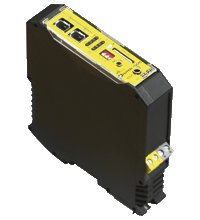
AS-Interface safety module VBA-2E-KE4-ENC-S
- SIL3 (EN 62061)
- Addressing jack
- Memory card for configuration data
Please note: All product-related documents, such as certificates, declarations of conformity, etc., which were issued prior to the conversion under the name Pepperl+Fuchs GmbH or Pepperl+Fuchs AG, also apply to Pepperl+Fuchs SE.
Tam veri sayfasını PDF olarak indirin:
Veri sayfası alıntısı: Teknik veriler VBA-2E-KE4-ENC-S
| Ürün Açıklaması |
|---|
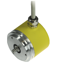
| KE4 control cabinet module 2 inputs for incremental rotary encoders |
| General specifications | ||
|---|---|---|
| Node type | A/B node | |
| AS-Interface specification | V3.0 | |
| Required gateway specification | ≥ V3.0 | |
| UL File Number | E223772 | |
| Functional safety related parameters | ||
| Safety Integrity Level (SIL) | SIL 3 | |
| Performance level (PL) | PL e | |
| Mission Time (TM) | 20 a | |
| PFHd | 2.77 E-9 | |
| Indicators/operating means | ||
| LED FAULT | error display; LED red red: communication error |
|
| LED AS-i | AS-Interface voltage; LED green | |
| LED AUX | ext. auxiliary voltage UAUX ; LED green | |
| LED CONF | Off = Normal mode, yellow LED | |
| LED STATE | Status of rotary encoder, 2 yellow LEDs | |
| LED FREQUENCY | Low frequency or halt, 2 LED yellow | |
| Electrical specifications | ||
| Auxiliary voltage (input) | 18 … 30 VDC | |
| Insulation voltage | 500 V AS-Interface/UAUX: | |
| Rated operating voltage | 18,0 ... 31.6 V from AS-Interface | |
| Rated operating current | ≤ 150 mA from AS-Interface; ≤ 200 mA from AUX |
|
| Interface 1 | ||
| Interface type | Chip card slot | |
| Input | ||
| Number/Type | 2 inputs for incremental rotary encoders AMP mini-IO connector |
|
| Voltage | Ub = 5 V DC | |
| Signal delay | 100 ms at 1015 Hz < flimit 140 ms at 45 Hz < flimit < 1015 Hz 700 ms at flimit < 45 Hz |
|
| Signal frequency | Parameterization range 25 Hz … 200 kHz | |
| Current | ≤ 100 mA | |
| Directive conformity | ||
| Electromagnetic compatibility | ||
| Directive 2014/30/EU | EN 62026-2:2013 | |
| Standard conformity | ||
| Degree of protection | EN 60529:2000 | |
| Electrical safety | EN 954-1:1996 (up to Kategorie 4), EN 62061:2005 (up to SIL3) EN ISO 13849-1:2006 to PL e | |
| Input | EN 61131-2:2007 | |
| AS-Interface | EN 62026-2:2013 | |
| Programming instructions | ||
| Profile | Safe input slaves: S-0.B.E Diagnosis slaves: S-7.A.5. |
|
| IO code | 0 | |
| ID code | B | |
| ID1 code | F | |
| Ambient conditions | ||
| Ambient temperature | 0 ... 55 °C (32 ... 131 °F) | |
| Storage temperature | -25 ... 85 °C (-13 ... 185 °F) | |
| Mechanical specifications | ||
| Degree of protection | IP20 | |
| Connection | removable terminals rated connection capacity: rigid/flexible (with and without wire-end ferrules): 0.25 mm2 ... 2.5 mm2 for multiple-wire connection with two wires of equal cross-section: flexible with twin wire-end ferrules: 0.5 mm2 ... 1.5 mm2 |
|
| Material | ||
| Housing | PA 66-FR | |
| Dimensions | ||
| Height | 99 mm | |
| Width | 22.5 mm | |
| Length | 113 mm | |
| Mounting | DIN mounting rail | |
Classifications
| System | Classcode |
|---|---|
| ECLASS 13.0 | 27272603 |
| ECLASS 12.0 | 27242604 |
| ECLASS 11.0 | 27242604 |
| ECLASS 10.0.1 | 27242604 |
| ECLASS 9.0 | 27242604 |
| ECLASS 8.0 | 27242604 |
| ECLASS 5.1 | 27242604 |
| ETIM 9.0 | EC001599 |
| ETIM 8.0 | EC001599 |
| ETIM 7.0 | EC001599 |
| ETIM 6.0 | EC001599 |
| ETIM 5.0 | EC001599 |
| UNSPSC 12.1 | 39121535 |
Details: VBA-2E-KE4-ENC-S
Function
The AS-Interface rotational speed monitor VBA-2E-KE4-ENC-S is a safe control cabinet module with 2 inputs. The inputs comprise 2 safe inputs for incremental encoders. The rotational speed monitor monitors the standstill, rotational speed and direction of rotation on a maximum of two axes and sends a safe signal via the AS-Interface network when a value falls below the set threshold.
The housing, which is only 22.5 mm wide, requires little space in the switch cabinet. The module is installed by simply snapping it onto the 35 mm standard mounting rail to EN 50022. An addressing socket is integrated in the module.
The AS-Interface and external power supply are each connected by means of a 2-station terminal block. This permits the simple removal of the supply during commissioning or servicing. The supply to the rotary encoders is fed either internally via the module from the AS-Interface or via an external supply. The current status of the inputs is indicated via yellow LEDs. Communication faults are indicated via red LEDs. The display of the operating voltage and the address 0 is provided by a green LED.
The configuration data is saved on a chip card, making it easier to replace the module in the event of damage.
Product Documentation: VBA-2E-KE4-ENC-S
| Brief Instructions | Dil | Dosya Tipi | Dosya Boyutu |
|---|---|---|---|
| Mounting Instruction VBA-2E-KE4-ENC-S / Montageanleitung VBA-2E-KE4-ENC-S | ALL | 3682 KB | |
| Safety and Security Documentation | |||
| Instruction Manual VBA-2E-KE4-ENC-S / Betriebsanleitung VBA-2E-KE4-ENC-S | ALL | 1945 KB | |
| Manuals | |||
| Manual VBA-2E*-KE4-ENC* | ENG | 5045 KB | |
Design / Simulation: VBA-2E-KE4-ENC-S
| CAD | Dil | Dosya Tipi | Dosya Boyutu |
|---|---|---|---|
| CAD 3-D / CAD 3-D | ALL | STP | 2364 KB |
| CAD Portal / CAD Portal | ALL | LINK | --- |
| CAE | |||
| CAE EPLAN Data Portal / CAE EPLAN Data Portal | ALL | LINK | --- |
| CAE EPLAN macro EDZ / CAE EPLAN Makro EDZ | ALL | EDZ | 37 KB |
Approvals: VBA-2E-KE4-ENC-S
| Certificates | Sertifika No. | Dil | Dosya Tipi | Dosya Boyutu |
|---|---|---|---|---|
| EU TUV Nord Functional Safety | 44 205 16 000805 | ALL | 1457 KB | |
| US CA UL | E223772 | ALL | LINK | --- |
| Declaration of Conformity | ||||
| EU Declaration of Conformity (P+F) / EU-Konformitäterklärung (P+F) | DOC-2490E | ALL | 213 KB | |
Software: VBA-2E-KE4-ENC-S
| Software Tools | Sürüm Bilgileri | Dosya Tipi | Dosya Boyutu |
|---|---|---|---|
| SISTEMA SLB Library AS-Interface Safety / SISTEMA SLB Library AS-Interface Safety | ZIP | 622 KB |
İlişkili Ürünler: VBA-2E-KE4-ENC-S
| Matching System Components | ||||||
|---|---|---|---|---|---|---|
|
||||||
| Accessories | ||||||
|
||||||
|
||||||
|
||||||
|
||||||
|
||||||




 +90 216 577 2250