AS-Interface I/O module VBA-4E4A-G20-ZEJ/M48L-P12
- Inputs for 3-wire sensors
- A/B node with extended addressing possibility for up to 62 nodes
- Connection of motors and sensors via M8 connectors
- Power supply of outputs from auxiliary voltage AUX
- Supply for inputs from AS-Interface
- Cable piercing method with gold plated contact pins
- Outputs for 48 V DC roller motors
Please note: All product-related documents, such as certificates, declarations of conformity, etc., which were issued prior to the conversion under the name Pepperl+Fuchs GmbH or Pepperl+Fuchs AG, also apply to Pepperl+Fuchs SE.
Pobierz pełną kartę katalogową w formie pliku PDF:
Dane techniczne VBA-4E4A-G20-ZEJ/M48L-P12
| Opis produktu |
|---|
| G20 motor control module for Interroll EC5000 48V AI |
| General specifications | ||
|---|---|---|
| Node type | A/B node | |
| AS-Interface specification | V3.0 | |
| Required gateway specification | ≥ V3.0 | |
| Profile | S-7.A.7 | |
| IO code | 7 | |
| ID code | A | |
| ID1 code | 7 | |
| ID2 code | 7 | |
| UL File Number | E223772 "For use in NFPA 79 Applications only" | |
| MTBF | 98 a | |
| Compatible roller motors | Interroll EC5000 48V AI (20W / 35W / 50W), | |
| Indicators/operating means | ||
| LED FAULT | error display; LED red red: communication error or address is 0 red flashing: overload of sensor supply or speed signal overload or external auxiliary voltage UAUX missing |
|
| LED ERR | Motor fault: 2 LED yellow | |
| LED PWR | AS-Interface voltage; green LED green: voltage OK green flashing: address 0 or sensor supply overload or speed signal overload or external auxiliary voltage UAUX missing |
|
| LED AUX | ext. auxiliary voltage UAUX; dual LED green/red green: voltage OK red: reverse voltage |
|
| LED IN | switching state (input); 2 LED yellow | |
| LED FUSE | Motor power supply; 2 green LEDs | |
| LED DIR | Motor rotation direction; yellow LED | |
| LED MOT | Motor active; 2 yellow LEDs | |
| Electrical specifications | ||
| Auxiliary voltage (output) | 36 ... 56 V DC PELV | |
| Rated operating voltage | 26.5 ... 31.6 V from AS-Interface | |
| Rated operating current | ≤ 25 mA (without sensors) / max. 170 mA | |
| Input | ||
| Number/Type | 2 Inputs for 3-wire sensors (PNP), DC | |
| Supply | from AS-Interface | |
| Current loading capacity | 100 mA , overload and short-circuit protected | |
| Input current | ≤ 6 mA (internally limited) | |
| Switching point | according to DIN EN 61131-2 0 (undamped) ≤ 0.5 mA 1 (damped) ≥ 2.0 mA |
|
| Signal delay | < 1 ms (input/AS-Interface) | |
| Input filter | 2 ms | |
| Output | ||
| Number/Type | 2 outputs for DC roller motors (MOT1, MOT2) | |
| Supply | from external auxiliary voltage UAUX | |
| Current | 3.5 A continuous current , 5 A (<2 s) , max. 7.5 A (<0,3 s) per motor | |
| Overload protection | Fuse 4 A, I2t = 122.5 A2s per motor | |
| Velocity signal | 0 ... 10 V DC Control via parameter P1:0 |
|
| Rotation direction signal | PNP digital output low: high impedance high: ≥ 15 V |
|
| Motor fault | NPN digital input 0 (no error) ≥ 125 µA 1 (error) ≤ 25 µA |
|
| Directive conformity | ||
| Electromagnetic compatibility | ||
| Directive 2014/30/EU | EN 62026-2:2013+A1:2019 | |
| Standard conformity | ||
| Degree of protection | EN 60529:2000 | |
| Fieldbus standard | EN 62026-2:2013 | |
| Input | EN 61131-2:2007 | |
| Emitted interference | EN 61000-6-4:2007 , EN 55011:2016+A1:2017+A11:2020 | |
| AS-Interface | EN 62026-2:2013+A1:2019 | |
| Noise immunity | EN 61000-6-2:2019 , EN 61326-1:2021 , EN 62026-2:2013+A1:2019 | |
| Ambient conditions | ||
| Ambient temperature | -25 ... 65 °C (-13 ... 149 °F) | |
| Storage temperature | -25 ... 85 °C (-13 ... 185 °F) | |
| Relative humidity | 85 % non-condensing | |
| Climatic conditions | For indoor use only | |
| Altitude | ≤ 5000 m above MSL | |
| Shock and impact resistance | 30 g, 11 ms in 6 spatial directions, 3 shocks | |
| Vibration resistance | 0.35 mm / 2 g 10 ... 1000 Hz | |
| Pollution degree | 2 | |
| Mechanical specifications | ||
| Degree of protection | IP54 according to EN 60529 | |
| Connection | AS-Interface, AUX: Insulation piercing technology Yellow flat cable/black flat cable Inputs/outputs: M8 round plug connector in accordance with EN 61076-2-104 Inputs: LF004-GS1-A (4-pin, bushing contacts, screw lock, A-coded) Matching connector: LM004-Gx1-A or similar Outputs: NF005-SS1-B (5-pin, bushing contacts, snap lock, B-coded). Matching connector: NM005-Sx1-B or similar |
|
| Mass | 310 g | |
| Dimensions | ||
| Height | 27.5 mm | |
| Width | 131.5 mm | |
| Length | 54 mm | |
| Mounting | 2 clips with ∅ 8 mm drill hole | |
| Cable length | 1 m | |
| Note | The flat cable routing is designed for 100 actuation cycles | |
Classifications
| System | Classcode |
|---|---|
| ECLASS 13.0 | 27242604 |
| ECLASS 12.0 | 27242604 |
| ECLASS 11.0 | 27242604 |
| ECLASS 10.0.1 | 27242604 |
| ECLASS 9.0 | 27242604 |
| ECLASS 8.0 | 27242604 |
| ECLASS 5.1 | 27242604 |
| ETIM 9.0 | EC001599 |
| ETIM 8.0 | EC001599 |
| ETIM 7.0 | EC001599 |
| ETIM 6.0 | EC001599 |
| ETIM 5.0 | EC001599 |
| UNSPSC 12.1 | 39121535 |
Details: VBA-4E4A-G20-ZEJ/M48L-P12
Function
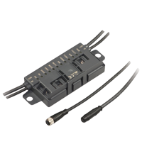
The AS-Interface connecting module is a field module with two sensor inputs and two electronic outputs for controlling DC roller motors of the type Interroll EC5000 48V AI.
The compact housing can be installed directly into support profiles or cable ducts. It is connected to the AS-Interface network and the auxiliary energy using insulation piercing technology via the AS-Interface flat cable. The swiveling flat cable guide is locked without the use of tools. The sensor inputs and motor outputs are connected using cable outputs with M8 round plug connectors. The inputs are supplied via the AS-Interface. The motors are supplied via the external auxiliary voltage U AUX.
The current switching state of the sensor inputs, the presence of supply voltage at the motors, the operating state of the motors (stationary/in operation), the direction of rotation, and the setting of the fault signal via a motor is displayed via LEDs.
Using AS-Interface data bits, the motors can be switched on or off individually, the direction of rotation can be changed, and the speed of the motor can be controlled. The voltage for the speed signal and a separate direction of rotation for motor 2 can be controlled via AS-Interface parameters.
To control the acceleration and to stop the motors, a start/stop ramp can be set for the speed signal. The time period of the ramp can be selected from eight preset values and can be configured. Once selected, the ramp is stored in non-volatile memory and automatically activated after each switch-on. The ramp is not effective if the direction of rotation signal is switched when the motor is running. In this case, the direction of rotation is reversed immediately.
Note:
The communication monitor of the module deactivates the outputs if the AS-Interface does not communicate with the module for more than 40 ms. Inputs IN1 and IN2 suppress pulses that are shorter than 2 ms. An overload of the input supply, an overload of the speed signal, or a lack of external auxiliary voltage is reported to the AS-Interface gateway via the "Peripheral error" function. The communication via AS-Interface remains unaffected.
Product Documentation: VBA-4E4A-G20-ZEJ/M48L-P12
| Brief Instructions | Język | Typ pliku | Rozmiar pliku |
|---|---|---|---|
| Instruction leaflet / Beipackzettel | ALL | 721 KB | |
| Manuals | |||
| Manual VBA-4E4A-G20-ZEJ/M48L-P12 | ENG | 990 KB | |
Approvals: VBA-4E4A-G20-ZEJ/M48L-P12
| Certificates | Nr. certyfikatu | Język | Typ pliku | Rozmiar pliku |
|---|---|---|---|---|
| US CA UL | CoC UL-US-L223772-13-82803102-1 | ALL | 175 KB | |
| Declaration of Conformity | ||||
| EU Declaration of Conformity (P+F) | TDOC-7400_POL | POL | 195 KB | |
| UK Declaration of Conformity (P+F) | TDOC-7401_ENG | ENG | 172 KB | |
Produkty powiązane: VBA-4E4A-G20-ZEJ/M48L-P12
| Accessories | ||||||
|---|---|---|---|---|---|---|
|
||||||
|
||||||
|
||||||
|
||||||
|
||||||
|
||||||
|
||||||




 +48 22 256 9770