

Not available for purchase
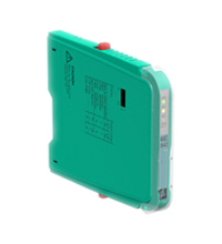
Switch Amplifier HiC2831R1
- 1-channel isolated barrier
- 24 V DC supply (bus powered)
- Dry contact or NAMUR inputs
- Application-specific outputs
- Usable as signal splitter (1 input and 2 outputs)
- 2 passive transistor outputs (resistive)
- Line fault transparency (LFT)
- Up to SIL 2 acc. to IEC 61508


 Contact Us
Please note: All product-related documents, such as certificates, declarations of conformity, etc., which were issued prior to the conversion under the name Pepperl+Fuchs GmbH or Pepperl+Fuchs AG, also apply to Pepperl+Fuchs SE.
Download the complete datasheet as a PDF:
Datasheet excerpt: Technical data of HiC2831R1
| General specifications | ||
|---|---|---|
| Signal type | Digital Input | |
| Supply | ||
| Connection | SL1: 1a(-), 1b(-); 2a(+), 2b(+) | |
| Rated voltage | 19 ... 30 V DC via Termination Board | |
| Ripple | ≤ 10 % | |
| Rated current | ≤ 25 mA | |
| Power dissipation | ≤ 500 mW | |
| Power consumption | ≤ 600 mW | |
| Input | ||
| Connection | SL2: 5a(+), 5b(-) | |
| Rated values | acc. to EN 60947-5-6 (NAMUR), see manual for electrical data | |
| Open circuit voltage/short-circuit current | approx. 10 V DC / approx. 8 mA | |
| Switching point/switching hysteresis | 1.2 ... 2.1 mA / approx. 0.2 mA | |
| Line fault detection | breakage I ≤ 0.1 mA , short-circuit I ≥ 6.5 mA | |
| Pulse/Pause ratio | min. 100 µs / min. 100 µs | |
| Output | ||
| Connection | SL1: 8a(+), 7a(-); 10a(+), 9a(-) | |
| Rated voltage | 19 ... 30 V DC with external resistance > 2 kΩ, e. g. 16-channel ProSafe DI card SDV144 from Yokogawa | |
| Response time | ≤ 200 µs | |
| Output I, II | signal or fault message, passive transistor output (resistive) 0-signal: 33 kΩ ± 5 % + voltage drop 6.5 V ± 0.5 V 1-signal: voltage drop 6.5 V ± 0.5 V fault: > 100 kΩ |
|
| Fault indication output | ||
| Connection | SL1: 6b | |
| Output type | open collector transistor (internal fault bus) | |
| Transfer characteristics | ||
| Switching frequency | ≤ 5 kHz | |
| Galvanic isolation | ||
| Output/power supply | basic insulation according to IEC/EN 61010-1, rated insulation voltage 60 Veff | |
| Output/Output | basic insulation according to IEC/EN 61010-1, rated insulation voltage 60 Veff | |
| Indicators/settings | ||
| Display elements | LED PWR ON (power supply), one green LED LED STATUS (output status), one bicolored LED (yellow) LED FAULT (lead fault), one bicolored LED (red) |
|
| Control elements | DIP switches at the housing side for: - mode of operation input - output - lead fault detection enable/disable |
|
| Labeling | space for labeling at the front | |
| Directive conformity | ||
| Electromagnetic compatibility | ||
| Directive 2014/30/EU | EN 61326-1:2013 (industrial locations) | |
| Conformity | ||
| Electromagnetic compatibility | NE 21:2012 , EN 61326-3-2:2008 | |
| Degree of protection | IEC 60529:2001 | |
| Protection against electrical shock | IEC 61010-1 | |
| Ambient conditions | ||
| Ambient temperature | -20 ... 60 °C (-4 ... 140 °F) | |
| Mechanical specifications | ||
| Degree of protection | IP20 | |
| Mass | approx. 100 g | |
| Dimensions | 12.5 x 106 x 128 mm (0.5 x 4.2 x 5.1 inch) | |
| Height | 128 mm | |
| Width | 12.5 mm | |
| Length | 106 mm | |
| Mounting | on termination board | |
| Coding | pin 1 and 2 trimmed For further information see system description. |
|
| Data for application in connection with hazardous areas | ||
| EU-type examination certificate | BVS 11 ATEX E 026 | |
| Marking |  II (1) G [Ex ia] IIC, II (1) D [Ex ia] IIIC I (M1) [Ex ia] I II (1) G [Ex ia] IIC, II (1) D [Ex ia] IIIC I (M1) [Ex ia] I |
|
| Input | Ex ia | |
| Voltage | 10.5 V | |
| Current | 17.1 mA | |
| Power | 45 mW (linear characteristic) | |
| Supply | ||
| Maximum safe voltage | 253 V AC (Attention! Um is no rated voltage.) | |
| Output | ||
| Maximum safe voltage | 253 V AC (Attention! Um is no rated voltage.) | |
| Certificate | KIWA 15 ATEX 0037 X | |
| Marking | II 3G Ex nA IIC T4 Gc |
|
| Galvanic isolation | ||
| Input/Output | safe electrical isolation acc. to IEC/EN 60079-11, voltage peak value 375 V | |
| Input/power supply | safe electrical isolation acc. to IEC/EN 60079-11, voltage peak value 375 V | |
| Directive conformity | ||
| Directive 2014/34/EU | EN 60079-0:2012+A11:2013 , EN 60079-11:2012 , EN 60079-15:2010 , EN 50303:2000 | |
| International approvals | ||
| UL approval | ||
| Control drawing | 116-0331 | |
| IECEx approval | IECEx BVS 11.0040 | |
| Approved for | [Ex ia Ga] IIC, [Ex ia] IIIC , [Ex ia] I | |
| General information | ||
| Supplementary information | EC-Type Examination Certificate, Statement of Conformity, Declaration of Conformity, Attestation of Conformity and instructions have to be observed where applicable. For information see www.pepperl-fuchs.com. | |
Classifications
| System | Classcode |
|---|---|
| ECLASS 13.0 | 27210121 |
| ECLASS 12.0 | 27210121 |
| ECLASS 11.0 | 27210121 |
| ECLASS 10.0.1 | 27210121 |
| ECLASS 9.0 | 27210121 |
| ECLASS 8.0 | 27210121 |
| ECLASS 5.1 | 27210121 |
| ETIM 9.0 | EC001485 |
| ETIM 8.0 | EC001485 |
| ETIM 7.0 | EC001485 |
| ETIM 6.0 | EC001485 |
| ETIM 5.0 | EC001485 |
| UNSPSC 12.1 | 32101514 |
Details: HiC2831R1
Product Documentation: HiC2831R1
| Safety and Security Documentation | Language | File Type | File Size |
|---|---|---|---|
| Instruction manual | ENG | 168 KB | |
| Functional Safety Manual | ENG | 2014 KB | |
| Manuals | |||
| System Manual | ENG | 5438 KB | |
Design / Simulation: HiC2831R1
| CAD | Language | File Type | File Size |
|---|---|---|---|
| CAD 2-D / CAD 2-D | ALL | ZIP | 16364 KB |
Approvals: HiC2831R1
| Certificates | Certificate No. | Language | File Type | File Size |
|---|---|---|---|---|
| Brasil TUV Rheinland Brazil | TÜV 16.0821 | ALL | 1136 KB | |
| Canada FM | FM 17 CA 0057X | ALL | 328 KB | |
| Europe KIWA ATEX Category 3 G | KIWA 15 ATEX 0037X | ALL | 988 KB | |
| KIWA IECEx Certificate of Conformity Zone 2 | IECEx KIWA 15.0019X | ALL | LINK | --- |
| Korea KOSHA | 15-AV4BO-0596 | ALL | 611 KB | |
| USA FM | FM 17 US 0111X | ALL | 330 KB | |
| Control Drawings | ||||
| Control drawing UL / Control drawing UL | ALL | 136 KB | ||

- Ask an Expert
- Cross Reference Request
- Check order status
- News
- NetPartner Login
- Subscribe to Gate-Way, our Process Automation Division e-newsletter
- Service Level Agreements for ecom instruments
- Find a Local Distributor or Representative
- Literature
- Technologies
- Control System Solutions
- Download Technical Documents
- Press Releases
- International Trade Shows

Choose from various selection criteria like safety integrity level, performance level, device function, and signal type and find the SIL/PL assessed device that you are looking for.


Pepperl+Fuchs Inc.
1600 Enterprise Parkway
Twinsburg, OH 44087
United States of America
sales@us.pepperl-fuchs.com
 +1 330 425-3555
Pepperl+Fuchs is a leading developer and manufacturer of electronic sensors and components for the global automation market. Continuous innovation, enduring quality, and steady growth have been the foundation of our success for more than 70 years. Pepperl+Fuchs employs 6,300 people worldwide and has manufacturing facilities in Germany, USA, Singapore, Hungary, Indonesia and Vietnam, most of them ISO 9001 certified. Pepperl+Fuchs does not sell personal data.