

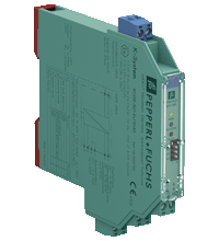
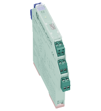
Solenoid Driver KCD2-SLD-Ex1.1045
- 1-channel isolated barrier
- 24 V DC supply (bus or loop powered)
- Output 45 mA at 10 V DC
- Line fault transparency (LFT)
- Test pulse immunity
- Housing width 12.5 mm
- Up to SIL 3 acc. to IEC 61508


Please note: All product-related documents, such as certificates, declarations of conformity, etc., which were issued prior to the conversion under the name Pepperl+Fuchs GmbH or Pepperl+Fuchs AG, also apply to Pepperl+Fuchs SE.
Faça o download das folhas de dados em PDF:
Folhas de dados: Dados técnicos do KCD2-SLD-Ex1.1045
| General specifications | ||
|---|---|---|
| Signal type | Digital Output | |
| Functional safety related parameters | ||
| Safety Integrity Level (SIL) | SIL 3 | |
| Supply | ||
| Connection | terminals 5+, 6- loop powered Power Rail or terminals 9+, 10- bus powered |
|
| Rated voltage | 19 ... 30 V DC loop powered |
|
| Input current | 75 mA at 24 V, 220 Ω load | |
| Power dissipation | 1.4 W at 24 V, 220 Ω load | |
| Input | ||
| Connection side | control side | |
| Connection | terminals 5+, 6- | |
| Test pulse length | max. 2 ms from DO card | |
| Signal level | loop powered 1-signal: 19 ... 30 V DC 0-signal: 0 ... 5 V DC bus powered 1-signal: 15 ... 30 V DC (current limited to 5 mA) 0-signal: 0 ... 5 V DC |
|
| Rated current | 0-signal: typ. 1.6 mA at 1.5 V DC; typ. 8 mA at 3 V DC (maximum leakage current DO card) 1-signal: ≥ 36 mA (minimum load current DO card) |
|
| Inrush current | < 200 mA , 10 ms loop powered | |
| Output | ||
| Connection side | field side | |
| Connection | terminals 1+, 2- | |
| Internal resistor | 285 Ω | |
| Current | typ. 45 mA | |
| Voltage | typ. 10 V | |
| Current limit | 45 mA | |
| Open loop voltage | typ. 24.6 V | |
| Load | nominal 0.05 ... 18 kΩ | |
| Output II | fault signal | |
| Connection | terminals 7, 8 , non-intrinsically safe | |
| Contact loading | 30 V DC/ 0.5 A resistive load | |
| Mechanical life | 105 switching cycles | |
| Energized/De-energized delay | ≤ 20 ms / ≤ 20 ms | |
| Line fault detection | signal at short-circuit Rload < 25 Ω, lead breakage Rload > 50 kΩ ; test current < 500 µA | |
| Galvanic isolation | ||
| Output/other circuits | basic insulation according to IEC/EN 61010-1, rated insulation voltage 300 Veff | |
| Output II/power supply | basic insulation according to IEC/EN 61010-1, rated insulation voltage 32 Veff | |
| Indicators/settings | ||
| Display elements | LEDs | |
| Control elements | DIP switch | |
| Configuration | via DIP switches | |
| Labeling | space for labeling at the front | |
| Directive conformity | ||
| Electromagnetic compatibility | ||
| Directive 2014/30/EU | EN 61326-1:2013 (industrial locations) | |
| Conformity | ||
| Electromagnetic compatibility | NE 21:2012 , EN 61326-3-2:2008 For further information see system description. |
|
| Degree of protection | IEC 60529:2013 | |
| Protection against electrical shock | EN 61010-1:2010 | |
| Ambient conditions | ||
| Ambient temperature | -20 ... 60 °C (-4 ... 140 °F) | |
| Mechanical specifications | ||
| Degree of protection | IP20 | |
| Connection | screw terminals | |
| Mass | approx. 150 g | |
| Dimensions | 12.5 x 119 x 114 mm (0.5 x 4.7 x 4.5 inch) , housing type A2 | |
| Height | 119 mm | |
| Width | 12.5 mm | |
| Length | 114 mm | |
| Mounting | on 35 mm DIN mounting rail acc. to EN 60715:2001 | |
| Data for application in connection with hazardous areas | ||
| EU-type examination certificate | EXA 17 ATEX 0002 X | |
| Marking |  II 3(1)G Ex nC ec [ia Ga] IIC T4 Gc II (1)D [Ex ia Da] IIIC I (M1) [Ex ia Ma] I II 3(1)G Ex nC ec [ia Ga] IIC T4 Gc II (1)D [Ex ia Da] IIIC I (M1) [Ex ia Ma] I |
|
| Output I | Ex ia | |
| Voltage | 26 V | |
| Current | 93 mA | |
| Power | 605 mW | |
| Supply | ||
| Maximum safe voltage | 60 V (Attention! The rated voltage can be lower.) | |
| Input | ||
| Maximum safe voltage | 60 V (Attention! The rated voltage can be lower.) | |
| Collective error message | ||
| Maximum safe voltage | 60 V (Attention! The rated voltage can be lower.) | |
| Galvanic isolation | ||
| Output I/other circuits | safe electrical isolation acc. to IEC/EN 60079-11, rated insulation voltage 300 Vrms | |
| Directive conformity | ||
| Directive 2014/34/EU | EN 60079-0:2012+A11:2013 , EN 60079-7:2015 , EN 60079-11:2012 , EN 60079-15:2010 | |
| International approvals | ||
| UL approval | E106378 | |
| Control drawing | 116-0448 (cULus) | |
| IECEx approval | ||
| IECEx certificate | IECEx EXA 17.0001X | |
| IECEx marking | Ex nC ec [ia Ga] IIC T4 Gc [Ex ia Da] IIIC [Ex ia Ma] I |
|
| General information | ||
| Supplementary information | Observe the certificates, declarations of conformity, instruction manuals, and manuals where applicable. For information see www.pepperl-fuchs.com. | |
| Accessories | ||
| Optional accessories | - power feed module KFD2-EB2(.R4A.B)(.SP) - universal power rail UPR-03(-M)(-S) - profile rail K-DUCT-BU(-UPR-03) |
|
Classifications
| System | Classcode |
|---|---|
| ECLASS 13.0 | 27210101 |
| ECLASS 12.0 | 27210190 |
| ECLASS 11.0 | 27210190 |
| ECLASS 10.0.1 | 27210190 |
| ECLASS 9.0 | 27210190 |
| ECLASS 8.0 | 27210190 |
| ECLASS 5.1 | 27210121 |
| ETIM 9.0 | EC001485 |
| ETIM 8.0 | EC001485 |
| ETIM 7.0 | EC001485 |
| ETIM 6.0 | EC001485 |
| ETIM 5.0 | EC001485 |
| UNSPSC 12.1 | 39121008 |
Details: KCD2-SLD-Ex1.1045
Product Documentation: KCD2-SLD-Ex1.1045
| Product information | Idioma | Tipo de Arquivo | Tamanho do Arquivo |
|---|---|---|---|
| Application Guideline Solenoid Drivers | ENG | 734 KB | |
| Safety and Security Documentation | |||
| Manual de instruções | POR | 166 KB | |
| Functional Safety Manual | ENG | 435 KB | |
| Manuals | |||
| Manual | ENG | 3685 KB | |
Design / Simulation: KCD2-SLD-Ex1.1045
| CAD | Idioma | Tipo de Arquivo | Tamanho do Arquivo |
|---|---|---|---|
| CAD 2-D / CAD 2-D | ALL | ZIP | 458 KB |
| CAD 3-D / CAD 3-D | ALL | STP | 179 KB |
| CAD Portal / CAD Portal | ALL | LINK | --- |
| CAE | |||
| CAE EPLAN Data Portal / CAE EPLAN Data Portal | ALL | LINK | --- |
| CAE EPLAN macro EDZ / CAE EPLAN Makro EDZ | ALL | EDZ | 70 KB |
Approvals: KCD2-SLD-Ex1.1045
| Certificates | Número do Certificado | Idioma | Tipo de Arquivo | Tamanho do Arquivo |
|---|---|---|---|---|
| Brasil TUV Rheinland Brazil | TÜV 21.1182 X | ALL | 1240 KB | |
| China SITIIAS CCC Ex Certificate | 2021322316003612 (Singapore) | ALL | 1300 KB | |
| DNV Marine | TAA00001WX | ALL | 106 KB | |
| EXA IECEx Certificate of Conformity | IECEx EXA 17.0001X | ALL | LINK | --- |
| Europe EXA ATEX Category (1) D ATEX ATEX Category (M1) ATEX Category (1) G ATEX Category 3 G | EXA 17 ATEX 0002X | ALL | 2278 KB | |
| Japan CML | CML 23JPN2001X | ALL | 276 KB | |
| Korea KOSHA | 23-AV4BO-0173X | ALL | 691 KB | |
| USA Canada UL Hazardous Location Certificate of Compliance cULus UL E106378 | CoC E106378 RepRef E106378-20181130 | ALL | 414 KB | |
| United Kingdom CML UKEX Category (1) D UKEX Category (M1) UK-Type Examination Certificate UKEX Category 3 (1) G | CML 21UKEX2891X | ALL | 308 KB | |
| Control Drawings | ||||
| Control drawing UL / Control drawing UL | ALL | 89 KB | ||
| Declaration of Conformity | ||||
| EU Declaration of Conformity (P+F) / EU-Konformitäterklärung (P+F) | DOC-3545C | ALL | 88 KB | |
Produtos Relacionados: KCD2-SLD-Ex1.1045
| Matching System Components | ||||||
|---|---|---|---|---|---|---|
|
||||||
|
||||||
|
||||||
|
||||||
|
||||||
|
||||||
| Accessories | ||||||
|
||||||
|
||||||
|
||||||


Choose from various selection criteria like safety integrity level, performance level, device function, and signal type and find the SIL/PL assessed device that you are looking for.


Pepperl+Fuchs Ltda.
Rua José Versolato, 111
Domo Corporate Tower, Conjunto 144
09750-730 São Bernardo do Campo, SP
Brasil
vendas@br.pepperl-fuchs.com
 +55 11 4007 1448
A Pepperl+Fuchs é líder na fabricação e no desenvolvimento de sensores e componentes eletrônicos para o setor global da automação industrial. Inovação contínua, qualidade e crescimento constante garantem o nosso sucesso há mais de 70 anos. Empregamos mais de 6.300 colaboradores em todo o mundo e contamos com fábricas próprias na Alemanha, Estados Unidos, Cingapura, Hungria, Indonésia e Vietnã, todas com certificação ISO 9001.