No disponible para compra
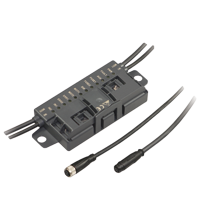
AS-Interface I/O module VBA-4E4A-G20-ZEJ/M3L-P9
- A/B node with extended addressing possibility for up to 62 nodes
- Inputs for 3-wire sensors
- Outputs for DC roller motors (drum motors)
- Connection of motors and sensors via M8 connectors
- Configurable start/stop ramps
- Communication monitoring
- Power supply of outputs from the external auxiliary voltage
- Supply for inputs from AS-Interface
- Function display for bus, external auxiliary voltage, in- and outputs
- Cable piercing method with gold plated contact pins
Please note: All product-related documents, such as certificates, declarations of conformity, etc., which were issued prior to the conversion under the name Pepperl+Fuchs GmbH or Pepperl+Fuchs AG, also apply to Pepperl+Fuchs SE.
Descargue la hoja de datos completa en PDF:
Extracto de la hoja de datos: Información técnica del VBA-4E4A-G20-ZEJ/M3L-P9
| Descripción del producto |
|---|
| G20 motor control module for Interroll EC310, Interoll EC5000 24V AI, Rulmeca BL3, Itoh Denki PM500XK, Itoh Denki PM500XC |
| General specifications | ||
|---|---|---|
| Node type | A/B node | |
| AS-Interface specification | V3.0 | |
| Required gateway specification | ≥ V3.0 | |
| Profile | S-7.A.7 | |
| IO code | 7 | |
| ID code | A | |
| ID1 code | 7 | |
| ID2 code | 7 | |
| UL File Number | E223772 "For use in NFPA 79 Applications only" | |
| MTBF | 98 a | |
| Compatible roller motors | Interroll EC310, Interroll EC5000 24V AI (20W / 35W / 50W), Rulmeca BL3, Itoh Denki PM500XK, Itoh Denki PM500XC | |
| Indicators/operating means | ||
| LED FAULT | error display; LED red red: communication error or address is 0 red flashing: overload of sensor supply or speed signal overload or external auxiliary voltage UAUX missing |
|
| LED ERR | Motor fault: 2 LED yellow | |
| LED PWR | AS-Interface voltage; green LED green: voltage OK green flashing: address 0 or sensor supply overload or speed signal overload or external auxiliary voltage UAUX missing |
|
| LED AUX | ext. auxiliary voltage UAUX; dual LED green/red green: voltage OK red: reverse voltage |
|
| LED IN | switching state (input); 2 LED yellow | |
| LED FUSE | Motor power supply; 2 green LEDs | |
| LED DIR | Motor rotation direction; yellow LED | |
| LED MOT | Motor active; 2 yellow LEDs | |
| Electrical specifications | ||
| Auxiliary voltage (output) | 18 ... 30 VDC PELV | |
| Rated operating voltage | 26.5 ... 31.6 V from AS-Interface | |
| Rated operating current | ≤ 25 mA (without sensors) / max. 170 mA | |
| Input | ||
| Number/Type | 2 Inputs for 3-wire sensors (PNP), DC | |
| Supply | from AS-Interface | |
| Current loading capacity | 100 mA , overload and short-circuit protected | |
| Input current | ≤ 6 mA (internally limited) | |
| Switching point | according to DIN EN 61131-2 0 (undamped) ≤ 0.5 mA 1 (damped) ≥ 2.0 mA |
|
| Signal delay | < 1 ms (input/AS-Interface) | |
| Input filter | 2 ms | |
| Output | ||
| Number/Type | 2 outputs for DC roller motors (MOT1, MOT2) | |
| Supply | from external auxiliary voltage UAUX | |
| Current | 3.5 A continuous current , 5 A (<2 s) , max. 7.5 A (<0,3 s) per motor | |
| Overload protection | fuse , I2t = 53.7 A2s | |
| Velocity signal | 0 ... 10 V DC Control via parameter P1:0 |
|
| Rotation direction signal | PNP digital output low: high impedance high; ≥ (VAUX - 2.5 V) in no-load operation |
|
| Motor fault | NPN digital input 0 (no error) ≥ 125 µA 1 (error) ≤ 25 µA |
|
| Directive conformity | ||
| Electromagnetic compatibility | ||
| Directive 2014/30/EU | EN 62026-2:2013 | |
| Standard conformity | ||
| Degree of protection | EN 60529:2000 | |
| Fieldbus standard | EN 62026-2:2013 | |
| Input | EN 61131-2:2007 | |
| Emitted interference | EN 61000-6-4:2007 | |
| AS-Interface | EN 62026-2:2013 | |
| Noise immunity | EN 61000-6-2:2005, EN 61326-1:2006, EN 62026-2:2013 | |
| Ambient conditions | ||
| Ambient temperature | -25 ... 70 °C (-13 ... 158 °F) | |
| Storage temperature | -25 ... 85 °C (-13 ... 185 °F) | |
| Relative humidity | 85 % non-condensing | |
| Climatic conditions | For indoor use only | |
| Altitude | ≤ 2000 m above MSL | |
| Shock and impact resistance | 30 g, 11 ms in 6 spatial directions, 3 shocks | |
| Vibration resistance | 0.35 mm / 2 g 10 ... 1000 Hz | |
| Pollution degree | 2 | |
| Mechanical specifications | ||
| Degree of protection | IP54 according to EN 60529 | |
| Connection | AS-Interface, AUX: Insulation piercing technology Yellow flat cable/black flat cable Inputs/outputs: M8 round plug connector in accordance with EN 61076-2-104 Inputs: LF004-GS1-A (4-pin, bushing contacts, screw lock, A-coded) Matching connector: LM004-Gx1-A or similar Outputs: NF005-SS1-B (5-pin, bushing contacts, snap lock, B-coded). Matching connector: NM005-Sx1-B or similar |
|
| Mass | 310 g | |
| Dimensions | ||
| Height | 27.5 mm | |
| Width | 131.5 mm | |
| Length | 54 mm | |
| Mounting | 2 clips with ∅ 8 mm drill hole | |
| Cable length | 1 m | |
| Note | The flat cable routing is designed for 100 actuation cycles | |
Classifications
| System | Classcode |
|---|---|
| ECLASS 13.0 | 27242604 |
| ECLASS 12.0 | 27242604 |
| ECLASS 11.0 | 27242604 |
| ECLASS 10.0.1 | 27242604 |
| ECLASS 9.0 | 27242604 |
| ECLASS 8.0 | 27242604 |
| ECLASS 5.1 | 27242604 |
| ETIM 9.0 | EC001599 |
| ETIM 8.0 | EC001599 |
| ETIM 7.0 | EC001599 |
| ETIM 6.0 | EC001599 |
| ETIM 5.0 | EC001599 |
| UNSPSC 12.1 | 39121535 |
Details: VBA-4E4A-G20-ZEJ/M3L-P9
Función
El módulo de conexión AS-Interface es un módulo de campo con dos entradas de sensor y dos salidas electrónicas para controlar rodillos accionados por motor de CC del tipo Interroll EC310, Rumelca BL3 o cualquiera que sea compatible.
La carcasa compacta se puede instalar directamente en los perfiles de soporte o en las canaletas. Se conecta a la red AS-Interface y a la corriente auxiliar mediante tecnología de perforación de aislamiento con un cable AS-Interface plano. La guía giratoria del cable plano se bloquea sin necesidad de herramientas. Las entradas de sensores y las salidas de motores se conectan mediante salidas de cable con conectores macho M8 redondos. Las salidas se alimentan a través de AS-Interface. Los motores se alimentan mediante la tensión auxiliar externa U AUX.
El estado de conmutación actual de las entradas de sensores, la presencia de tensión de alimentación en los motores, el estado operativo de los motores (parado/en funcionamiento), el sentido de giro y el ajuste de la señal de fallo a través de un motor se muestran mediante indicadores LED.
Con los bits de datos de AS-Interface, se pueden encender y apagar los motores de forma individual, cambiar el sentido de giro y controlar la velocidad del motor. La tensión para la señal de velocidad y un sentido de giro independiente para el motor 2 se pueden controlar mediante parámetros de AS-Interface.
Para controlar la aceleración y parar los motores, se puede establecer una rampa de arranque/parada para la señal de velocidad. El periodo de tiempo de la rampa puede seleccionarse entre ocho valores preestablecidos o configurarse. Una vez seleccionada, la rampa se guarda en la memoria no volátil y se activa automáticamente con cada encendido. La rampa no se activará si se conmuta la señal de sentido de giro mientras el motor está en marcha. En este caso, el sentido de giro se invertirá inmediatamente.
Nota:
El monitor de comunicación del módulo desactiva las salidas si AS-Interface no se comunica con el módulo durante más de 40 ms. Las entradas IN1 e IN2 suprimen los pulsos que duran menos de 2 ms. Cualquier sobrecarga de la alimentación de entrada, sobrecarga de la señal de velocidad o falta de tensión auxiliar externa se comunicará a la pasarela de AS-Interface mediante la función "Error de periférico". La comunicación a través de AS-Interface no se verá afectada.
Informative Literature: VBA-4E4A-G20-ZEJ/M3L-P9
| Literature | Idioma | Tipo de archivo | Tamaño |
|---|---|---|---|
| Portfolio overview G20 modules / Portfolio-Übersicht G20-Module | ALL | 121 KB |
Product Documentation: VBA-4E4A-G20-ZEJ/M3L-P9
| Brief Instructions | Idioma | Tipo de archivo | Tamaño |
|---|---|---|---|
| Instruction leaflet / Beipackzettel | ALL | 721 KB | |
| Manuals | |||
| Manual VBA-4E4A-G20-ZEJ/M3L-P9 | ENG | 974 KB | |
Design / Simulation: VBA-4E4A-G20-ZEJ/M3L-P9
| CAD | Idioma | Tipo de archivo | Tamaño |
|---|---|---|---|
| CAD 3-D / CAD 3-D | ALL | STP | 1692 KB |
| CAE | |||
| CAE EPLAN Data Portal / CAE EPLAN Data Portal | ALL | LINK | --- |
| CAE EPLAN macro EDZ / CAE EPLAN Makro EDZ | ALL | EDZ | 404 KB |
Approvals: VBA-4E4A-G20-ZEJ/M3L-P9
| Certificates | Número de Certificado | Idioma | Tipo de archivo | Tamaño |
|---|---|---|---|---|
| US CA UL | CoC UL-US-L223772-13-82803102-1 | ALL | 175 KB | |
| Worldwide AS-International Association AS-Interface | 129801 | ALL | 71 KB |
Software: VBA-4E4A-G20-ZEJ/M3L-P9
| Device Description Files/Drivers | Liberar Info | Tipo de archivo | Tamaño |
|---|---|---|---|
| Add-On Instructions for RSLogix/Studio 5000 / Add-On-Befehle für RSLogix/Studio 5000 | 4/2020 | ZIP | 23385 KB |
Productos asociados: VBA-4E4A-G20-ZEJ/M3L-P9
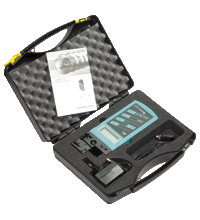
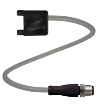
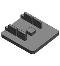
| Accessories | ||||||
|---|---|---|---|---|---|---|
|
||||||
|
||||||
|
||||||
Módulo de armario de conmutación AS-Interface KE5 – Manejo sencillo y manipulación mejorada

El diseño único de la carcasas del nuevo módulo de armario de conmutación KE5 permite una visibilidad superior y simplifica el montaje, cableado y mantenimiento dentro de los armarios de conmutación y cajas de conexiones.


 +49 621 776-0