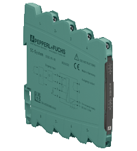
Rotation Speed Monitor S1SD-1FI-1R
- 1-channel signal conditioner
- 24 V DC supply
- Input for 2- or 3-wire sensors
- Input frequency 10 mHz ... 50 kHz
- Relay contact output
- Start-up override and restart inhibit
- Configurable by DIP switches and software
- Connection via screw terminals
Please note: All product-related documents, such as certificates, declarations of conformity, etc., which were issued prior to the conversion under the name Pepperl+Fuchs GmbH or Pepperl+Fuchs AG, also apply to Pepperl+Fuchs SE.
A teljes adatlap letöltése PDF formátumban:
Adatlap kivonata: Műszaki adatok S1SD-1FI-1R
| General specifications | ||
|---|---|---|
| Signal type | Digital Input | |
| Supply | ||
| Connection | Power Bus or terminals 1-, 2+ | |
| Rated voltage | 16.8 ... 31.2 V DC | |
| Power dissipation | 0.6 W | |
| Power consumption | 1.1 W | |
| Interface | ||
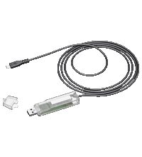
| Programming interface | programming socket | |
| Input | ||
| Connection side | field side | |
| NAMUR sensor | ||
| Type | 2-wire | |
| Connection | terminals 5+, 6 | |
| Signal | acc. to EN 60947-5-6 (NAMUR) | |
| Sensor supply | 8 V | |
| Open-circuit | < 0.1 mA | |
| Switching point | 1.2 ... 2.1 mA | |
| Short-circuit | > 6 mA | |
| Input impedance | 1 kΩ | |
| Mechanical contact | ||
| Type | 2-wire | |
| Connection | terminals 5+, 6 | |
| Sensor supply | 15 V | |
| External supply | ≤ 32 V | |
| Switching point | 8 ... 10 V / 1.2 ... 2.1 mA | |
| Frequency | 0 ... 50 Hz , debounce filter | |
| Input impedance | 4 kΩ | |
| SN sensor | ||
| Type | 2-wire | |
| Connection | terminals 5+, 6 | |
| Sensor supply | 8 V | |
| Open-circuit | < 0.1 mA | |
| Switching point | 1.2 ... 2.1 mA | |
| Short-circuit | > 6 mA | |
| Input impedance | 1 kΩ | |
| 2-wire DC sensor | ||
| Type | 2-wire | |
| Connection | terminals 5+, 6 | |
| Signal | acc. to EN 60947-5-2 | |
| Sensor supply | 16 V / 25 mA , short-circuit protected | |
| External supply | ≤ 32 V | |
| Switching point | 2 ... 5 mA | |
| Input impedance | 1 kΩ | |
| S0 sensor | ||
| Type | 2-wire | |
| Connection | terminals 5+, 6 | |
| Signal | acc. to EN 62053-31 , Type B | |
| Sensor supply | 15 V | |
| Switching point | 0.15 ... 2 mA | |
| Input impedance | 4 kΩ | |
| NPN sensor | ||
| Type | 3-wire | |
| Connection | terminals 5+, 6, 7- | |
| Signal | acc. to EN 60947-5-2 | |
| Sensor supply | 16 V / 25 mA , short-circuit protected | |
| External supply | ≤ 32 V | |
| Switching point | 3 ... 5 V | |
| Input impedance | 4 kΩ | |
| PNP sensor | ||
| Type | 3-wire | |
| Connection | terminals 5+, 6, 7- | |
| Signal | acc. to EN 60947-5-2 | |
| Sensor supply | 16 V / 25 mA , short-circuit protected | |
| External supply | ≤ 32 V | |
| Switching point | 8 ... 10 V | |
| Input impedance | 4 kΩ | |
| AC/DC voltage source | ||
| Connection | terminals 6, 7- | |
| Signal | max. ± 30 V | |
| Switching point | 150 ... 400 mV | |
| Input impedance | 4 kΩ | |
| Function input | ||
| Connection | terminal 8 | |
| Open loop voltage | 7.5 V | |
| Input impedance | approx. 50 kΩ | |
| Function 1 | activation start-up override | |
| Switching point | < 3 V , edge triggered | |
| Adjustment range | 1 ... 6500 s | |
| Function 2 | reset restart inhibit | |
| Switching point | > 12 V , edge triggered | |
| Output | ||
| Connection side | control side | |
| Connection | terminals 3, 4: | |
| Output | signal, relay | |
| Contact loading | 253 V AC/2 A/cos φ > 0.7; 126.5 V AC/4 A/cos φ > 0.7; 30 V DC/2 A resistive load | |
| Minimum switch current | 2 mA / 24 V DC | |
| Energized/De-energized delay | ≤ 20 ms / ≤ 20 ms | |
| Mechanical life | 107 switching cycles | |
| Transfer characteristics | ||
| Accuracy | max. 0.1 % of the measurement value | |
| Measuring time | ≤ 100 ms | |
| Influence of ambient temperature | < 100 ppm/K of the measured value | |
| Frequency range | 0.01 ... 50000 Hz | |
| Galvanic isolation | ||
| Output/power supply | safe electrical isolation by reinforced insulation according to IEC/EN 61010-1, rated insulation voltage 300 Veff test voltage 3 kV, 50 Hz, 1 min | |
| Input/Other circuits | safe electrical isolation by reinforced insulation according to IEC/EN 61010-1, rated insulation voltage 300 Veff test voltage 3 kV, 50 Hz, 1 min | |
| Indicators/settings | ||
| Display elements | LEDs | |
| Control elements | DIP switch | |
| Configuration | via DIP switches via software |
|
| Labeling | space for labeling at the front | |
| Directive conformity | ||
| Electromagnetic compatibility | ||
| Directive 2014/30/EU | EN 61326-1:2013 (industrial locations) | |
| Low voltage | ||
| Directive 2014/35/EU | EN 61010-1:2010 | |
| Conformity | ||
| Degree of protection | IEC 60529:2001 | |
| Protection against electrical shock | EN 61010-1:2010 | |
| Ambient conditions | ||
| Ambient temperature | -25 ... 70 °C (-13 ... 158 °F) | |
| Storage temperature | -40 ... 85 °C (-40 ... 185 °F) | |
| Damaging gas | designed for operation in environmental conditions acc. to ISA-S71.04-1985, severity level G3 | |
| Mechanical specifications | ||
| Degree of protection | IP20 | |
| Connection | screw terminals | |
| Core cross section | 0.5 ... 2.5 mm2 (20 ... 14 AWG) | |
| Mass | approx. 60 g | |
| Dimensions | 6.2 x 97 x 107 mm (0.24 x 3.82 x 4.21 inch) (W x H x D) , housing type S1 | |
| Height | 97 mm | |
| Width | 6.2 mm | |
| Depth | 107 mm | |
| Mounting | on 35 mm DIN mounting rail acc. to EN 60715:2001 | |
| General information | ||
| Supplementary information | Observe the certificates, declarations of conformity, instruction manuals, and manuals where applicable. For information see www.pepperl-fuchs.com. | |
Classifications
| System | Classcode |
|---|---|
| ECLASS 13.0 | 27210128 |
| ECLASS 12.0 | 27210128 |
| ECLASS 11.0 | 27210128 |
| ECLASS 10.0.1 | 27210128 |
| ECLASS 9.0 | 27210128 |
| ECLASS 8.0 | 27210190 |
| ECLASS 5.1 | 27210121 |
| ETIM 9.0 | EC002918 |
| ETIM 8.0 | EC002918 |
| ETIM 7.0 | EC002918 |
| ETIM 6.0 | EC002918 |
| ETIM 5.0 | EC002475 |
| UNSPSC 12.1 | 39121007 |
Details: S1SD-1FI-1R
Function
This signal conditioner provides the galvanic isolation between field circuits and control circuits.
The device monitors the overspeed condition and the underspeed condition of a digital signal.
The device has an input for the following digital signals:
-
Mechanical contacts
-
2-wire sensors (NAMUR, SN, DC, S0)
-
3-wire sensors (NPN, PNP)
-
AC/DC voltage sources (magnetic sensors)
-
custom-specific setting
The input is reverse polarity protected and short-circuit proofed.
The connected sensors can also be supplied externally.
The device compares the input frequency with a user-specified reference frequency. An overspeed condition or an underspeed condition is signaled via the relay contact outputs.
A fault is indicated by a red LED.
The device is easily configured by the use of DIP switches or software.
The device can be powered via terminals or Power Bus.
Informative Literature: S1SD-1FI-1R
| Literature | Nyelv | Fájltípus | Fájlméret |
|---|---|---|---|
| Application Report - Sand Trap and Preliminary Sedimentation Stage | ENG | 448 KB | |
| Product Overview SC-System | ENG | 456 KB | |
| Tender text | |||
| Tender text | ENG | D81 | 12 KB |
Product Documentation: S1SD-1FI-1R
| Brief Instructions | Nyelv | Fájltípus | Fájlméret |
|---|---|---|---|
| Brief instructions | ENG | 167 KB | |
| Safety and Security Documentation | |||
| Használati útmutató | HUN | 120 KB | |
| Manuals | |||
| System Manual | ENG | 2706 KB | |
Design / Simulation: S1SD-1FI-1R
| CAD | Nyelv | Fájltípus | Fájlméret |
|---|---|---|---|
| CAD 3-D / CAD 3-D | ALL | STP | 4814 KB |
| CAD Portal / CAD Portal | ALL | LINK | --- |
| CAE | |||
| CAE EPLAN Data Portal / CAE EPLAN Data Portal | ALL | LINK | --- |
| CAE EPLAN macro EDZ / CAE EPLAN Makro EDZ | ALL | EDZ | 82 KB |
| EPLAN macros SC-System devices (EDZ) / EPLAN-Makros SC-System-Geräte (EDZ) | ALL | ZIP | 4082 KB |
Approvals: S1SD-1FI-1R
| Declaration of Conformity | Tanúsítvány sz. | Nyelv | Fájltípus | Fájlméret |
|---|---|---|---|---|
| EU Declaration of Conformity (P+F) | TDOC-2695CHUN | HUN | 172 KB |
Software: S1SD-1FI-1R
| Software Tools | Megjelenési információ | Fájltípus | Fájlméret |
|---|---|---|---|
| Configuration software for SC-System: SC-Config / Konfigurations Software für SC-System: SC-Config | 3.4.0 | ZIP | --- |
Kapcsolódó termékek: S1SD-1FI-1R
| Matching System Components | ||||||
|---|---|---|---|---|---|---|
|
||||||
|
||||||
|
||||||
|
||||||
|
||||||
|
||||||
|
||||||





 +36 88 545 902