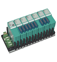
FOUNDATION Fieldbus Modular I/O FF MIO
- For 20 analog or 40 digital channels
- Sensors in Zone 0/Div. 1 (depending on module assembly)
- Installation in Zone 2 or safe area
- HART communication via service bus
- For FOUNDATION Fieldbus H1
- Configured via the process control system
- Non-volatile memory for configuration and parameter settings
- Quick communication set-up
- Permanently self-monitoring
- Outputs drive to safe state in case of failures
- Module can be exchanged under voltage
Please note: All product-related documents, such as certificates, declarations of conformity, etc., which were issued prior to the conversion under the name Pepperl+Fuchs GmbH or Pepperl+Fuchs AG, also apply to Pepperl+Fuchs SE.
A teljes adatlap letöltése PDF formátumban:
Adatlap kivonata: Műszaki adatok FF MIO
| Supply | ||
|---|---|---|
| Connection | backplane LB9035A | |
| Rated voltage | 24 V DC | |
| Power consumption | max. 39 W , available output power for Zone 2 applications 5 W (5V), 20 W (12V), else 5 W (5V), 35 W (12V) | |
| Auxiliary energy | 24 V DC Trunk load 10 mA according to FF standard. |
|
| Redundancy | no | |
| Fieldbus connection | ||
| FOUNDATION Fieldbus | ||
| Connection | plug-in screw connector on the backplane | |
| Baud rate | 31.25 kBit/s , MBP | |
| Protocol | H1 to IEC 1158-2 | |
| Station connection | directly at the trunk or via spur protector | |
| Number of stations per bus line | 1 or 2, depending on the required response times | |
| Number of channels per station | max. 20 analog, max. 40 digital | |
| Bus length | max. 1900 m (must not be exceeded by the sum of all trunk and spur lines) |
|
| Spur length | max. 120 m (depending on the number of field devices. Modular I/O station = 1 field device) |
|
| Addressing | via PCS (software) | |
| Redundancy | no | |
| Indicators/settings | ||
| LED indication | Com unit LB8110*: LED green (power supply): on = operating, fast flash = cold start LED red (collective alarm): on = internal fault, flashing = no fieldbus LED yellow (operating mode): flashing = active Power supply LB9006C: LED green (power supply): off in case of loss of 24 V or 12 V or 5 V I/O modules (refer to the table with compatible modules for order codes): Power LED green: supply Diagnostic LED red: module fault, red flashing: communication error Status LED red: line fault Status LED yellow: signal (Live Zero status) |
|
| Directive conformity | ||
| Electromagnetic compatibility | ||
| Directive 2004/108/EC | EN 61326-1 | |
| Conformity | ||
| Degree of protection | IEC 60529 | |
| Fieldbus standard | IEC 61158-2 | |
| Ambient conditions | ||
| Ambient temperature | -20 ... 60 °C (-4 ... 140 °F) | |
| Shock resistance | shock type I, shock duration 11 ms, shock amplitude 15 g, number of shocks 18 | |
| Vibration resistance | frequency range 10 ... 150 Hz; transition frequency: 57.56 Hz, amplitude/acceleration ± 0.075 mm/1 g; 10 cycles frequency range 5 ... 100 Hz; transition frequency: 13.2 Hz amplitude/acceleration ± 1 mm/0.7 g; 90 minutes at each resonance |
|
| Mechanical specifications | ||
| Degree of protection | IP20 | |
| Dimensions | 275 x 127 mm (10.8 x 5 inch) | |
| Data for application in connection with hazardous areas | ||
| Certificate | PF 08 CERT 1234 X | |
| Marking |  II 3 G Ex nA IIC T4 II 3 G Ex nA IIC T4 |
|
| Directive conformity | ||
| Directive 94/9/EC | EN 60079-0 , EN 60079-15 | |
| General information | ||
| System information | For use in hazardous areas (e. g. Zone 2, Zone 22 or Div. 2) an appropriate enclosure is required. | |
| Supplementary information | EC-Type Examination Certificate, Statement of Conformity, Declaration of Conformity, Attestation of Conformity and instructions have to be observed where applicable. For information see www.pepperl-fuchs.com. | |
Classifications
| System | Classcode |
|---|---|
| ECLASS 13.0 | 27210119 |
| ECLASS 12.0 | 27210119 |
| ECLASS 11.0 | 27210119 |
| ECLASS 10.0.1 | 27210119 |
| ECLASS 9.0 | 27210119 |
| ECLASS 8.0 | 27210119 |
| ECLASS 5.1 | 27210119 |
| ETIM 9.0 | EC001598 |
| ETIM 8.0 | EC001598 |
| ETIM 7.0 | EC001598 |
| ETIM 6.0 | EC001598 |
| ETIM 5.0 | EC001598 |
| UNSPSC 12.1 | 39121008 |
Details: FF MIO
Function
FF Modular I/O connects conventional field signals to FOUNDATION Fieldbus H1. It makes use of established reliable hardware and employs standard FF multi-function blocks. It supports NAMUR or switch type inputs as well as solenoid outputs, temperature signals or supply circuits for 2- or 4-wire transmitters, proportional valves and positioners. In contrast to dedicated digital input devices the FF Modular I/O combines analog and digital I/O in one device.
The modular approach enables a very compact solution, offering up to 40 digital, or 20 analog, or any combination of analog and digital inputs and outputs. The FF Modular I/O is installed locally near the instrumentation. The fieldbus cable serves as backbone. A selection of housing materials and accessories enables installation in Zone 2, Zone 22, Div. 2, or safe area.
Product Documentation: FF MIO
| Manuals | Nyelv | Fájltípus | Fájlméret |
|---|---|---|---|
| Hardware Manual LB-Remote-I/O-System | ENG | 5385 KB |
Kapcsolódó termékek: FF MIO
| Accessories | ||||||
|---|---|---|---|---|---|---|
|
||||||


 +36 88 545 902