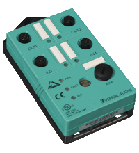
AS-Interface sensor/actuator module VAA-2EA-G2-ZA/EA2
- AS-Interface certificate
- Degree of protection IP67
- Addressing jack
- Flat cable connection with cable piercing technique, variable flat cable guide
- Communication monitoring
- Inputs for 2- and 3-wire sensors
- Power supply of outputs from the external auxiliary voltage
- Power supply of inputs from the module
- Function display for bus, ext. auxiliary voltage, inputs and outputs
- Monitoring of sensor overloads
Please note: All product-related documents, such as certificates, declarations of conformity, etc., which were issued prior to the conversion under the name Pepperl+Fuchs GmbH or Pepperl+Fuchs AG, also apply to Pepperl+Fuchs SE.
A teljes adatlap letöltése PDF formátumban:
Adatlap kivonata: Műszaki adatok VAA-2EA-G2-ZA/EA2
| Termék leírása |
|---|
| G2 flat module 2 inputs (PNP) and 2 electronic outputs |
| General specifications | ||
|---|---|---|
| Node type | Standard node | |
| AS-Interface specification | V3.0 | |
| Required gateway specification | ≥ V2.0 | |
| UL File Number | E223772 | |
| Indicators/operating means | ||
| LED FAULT | error display; LED red red: communication error or address is 0 red flashing: overload of sensor supply |
|
| LED PWR | AS-Interface voltage; LED green | |
| LED AUX | ext. auxiliary voltage UAUX ; LED green | |
| LED IN | switching state (input); 2 LED yellow | |
| LED OUT | Switching state (output); 2 LED yellow | |
| Electrical specifications | ||
| Auxiliary voltage (output) | 24 V DC ± 15 % PELV | |
| Rated operating voltage | 26.5 ... 31.6 V from AS-Interface | |
| Rated operating current | ≤ 40 mA (without sensors) / max. 190 mA | |
| Protection class | III | |
| Surge protection | UAUX, Uin: Over voltage category III, safe isolated power supplies (PELV) | |
| Input | ||
| Number/Type | 2 inputs for 2- or 3-wire sensors (PNP), DC | |
| Supply | from AS-Interface | |
| Voltage | 21 ... 31 V | |
| Current loading capacity | ≤ 150 mA (TB ≤ 40 °C), ≤ 120 mA (TB ≤ 60 °C), short-circuit protected |
|
| Input current | ≤ 8 mA (limited internally) | |
| Switching point | according to DIN EN 61131-2 (Type 2) | |
| 0 (unattenuated) | ≤ 1.5 mA | |
| 1 (attenuated) | ≥ 4.5 mA | |
| Signal delay | < 2 ms (input/AS-Interface) | |
| Signal frequency | ≤ 250 Hz | |
| Output | ||
| Number/Type | 2 electronic outputs, PNP | |
| Supply | from external auxiliary voltage UAUX | |
| Voltage | ≥ (UAUX - 0.5 V) | |
| Current | 1 A per output | |
| Directive conformity | ||
| Electromagnetic compatibility | ||
| Directive 2014/30/EU | EN 62026-2:2013 EN 61000-6-2:2001 EN 61000-6-4:2001 | |
| Standard conformity | ||
| Degree of protection | EN 60529:2000 | |
| Fieldbus standard | EN 62026-2:2013 | |
| Input | EN 61131-2:2007 | |
| Emitted interference | EN 61000-6-4:2001 | |
| AS-Interface | EN 62026-2:2013 | |
| Noise immunity | EN 61000-6-2:2001 | |
| Programming instructions | ||
| Profile | S-3.F | |
| IO code | 3 | |
| ID code | F | |
| ID1 code | F | |
| ID2 code | F | |
| Data bits (function via AS-Interface) | ||
| D0 | ||
| D1 | ||
| D2 | ||
| D3 | ||
| Parameter bits (programmable via AS-i) | function | |
| P0 | Communication monitoring P0 = 0 monitoring = off, the outputs maintain the status if communication fails P0 = 1 monitoring = on, i.e. if communication fails, the outputs are deenergised (default settings) |
|
| P1 | Input filter P1 = 0 input filter on, pulse suppression ≤ 2 ms P1 = 1 input filter off (default settings) |
|
| P2 | Synchronous mode P2 = 0 synchronous mode on P2 = 1 synchronous mode off (default settings) |
|
| P3 | not used | |
| Ambient conditions | ||
| Ambient temperature | -25 ... 60 °C (-13 ... 140 °F) | |
| Storage temperature | -25 ... 85 °C (-13 ... 185 °F) | |
| Relative humidity | 85 % , noncondensing | |
| Climatic conditions | For indoor use only | |
| Altitude | ≤ 2000 m above MSL | |
| Pollution degree | 3 | |
| Mechanical specifications | ||
| Degree of protection | IP67 | |
| Connection | Cable piercing method flat cable yellow/flat cable black inputs/outputs: M12 round connector |
|
| Material | ||
| Housing | PBT | |
| Mass | 100 g | |
| Tightening torque, cable gland | 0.4 Nm | |
| Mounting | Mounting plate | |
Classifications
| System | Classcode |
|---|---|
| ECLASS 13.0 | 27242604 |
| ECLASS 12.0 | 27242604 |
| ECLASS 11.0 | 27242604 |
| ECLASS 10.0.1 | 27242604 |
| ECLASS 9.0 | 27242604 |
| ECLASS 8.0 | 27242604 |
| ECLASS 5.1 | 27242604 |
| ETIM 9.0 | EC001599 |
| ETIM 8.0 | EC001599 |
| ETIM 7.0 | EC001599 |
| ETIM 6.0 | EC001599 |
| ETIM 5.0 | EC001599 |
| UNSPSC 12.1 | 39121535 |
Details: VAA-2EA-G2-ZA/EA2
Function
The VAA-2EA-G2-ZA/EA2 is an AS-Interface coupling module with 2 inputs and 2 outputs. Mechanical contacts and 2- and 3-wire sensors can be connected to the inputs. The outputs are electronic outputs, which can be loaded to 24 V DC and 1 A per output.
The IP67 flat module features an integrated addressing jack and is ideal for applications in the field.
Connection to sensors/actuators is provided via M12 x 1 screw connections. The current switching state of each channel is indicated by an LED located on the module's top side. Similarly, an LED is provided to monitor the AS-Interface communication and to indicate that the module has the address 0. If an AS-Interface communication error occurs, the outputs are de-energised.
The input circuit is monitored for short circuits. LEDs are also provided to indicate ASInterface voltage and external power supply.
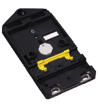
The U-G3FF mounting base is normally used for the connection of the AS-Interface flat cable and the external 24 V DC power supply. The specially designed base enables the user to connect flat cables from both sides.This means, for example, that 90° curves can be laid with very tight radii (variable flat cable guide).
Note:
The mounting base for the module is sold separately.
Product Documentation: VAA-2EA-G2-ZA/EA2
| Brief Instructions | Nyelv | Fájltípus | Fájlméret |
|---|---|---|---|
| Instruction leaflet / Beipackzettel | ALL | 188 KB |
Design / Simulation: VAA-2EA-G2-ZA/EA2
| CAD | Nyelv | Fájltípus | Fájlméret |
|---|---|---|---|
| CAD 3-D / CAD 3-D | ALL | STP | 149 KB |
| CAD Portal / CAD Portal | ALL | LINK | --- |
Approvals: VAA-2EA-G2-ZA/EA2
| Certificates | Tanúsítvány sz. | Nyelv | Fájltípus | Fájlméret |
|---|---|---|---|---|
| Canada, USA UL | CoC 20141115-E223772 | ALL | 342 KB | |
| Worldwide AS-International Association AS-Interface | 34101 | ALL | 608 KB | |
| Declaration of Conformity | ||||
| EU Declaration of Conformity (P+F) / EU-Konformitäterklärung (P+F) | DOC-1018C | ALL | 118 KB | |
Kapcsolódó termékek: VAA-2EA-G2-ZA/EA2
| Matching System Components | ||||||
|---|---|---|---|---|---|---|
|
||||||
| Accessories | ||||||
|
||||||
|
||||||
AS-Interfész KE5 kapcsolószekrény modul – Egyszerű kezelés és továbbfejlesztett kezelhetőség

Az új KE5 kapcsolószekrény modul egyedülálló házkialakítása jó láthatóságot biztosít, valamint leegyszerűsíti a felszerelést, vezetékezést és a szekrényeken belüli karbantartást.


 +36 88 545 902