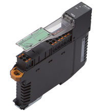
AS-Interface sensor/actuator module VAA-4E-KE5-ZEJQ-Y314458
- Housing with push-in connection technology and mechanically coded terminal blocks
- Housing width 19 mm, installation in the switch cabinet on DIN mounting rail
- Selectable supply to the sensors: External or from the module
- Function display for bus, internal sensor supply, and inputs
Please note: All product-related documents, such as certificates, declarations of conformity, etc., which were issued prior to the conversion under the name Pepperl+Fuchs GmbH or Pepperl+Fuchs AG, also apply to Pepperl+Fuchs SE.
A teljes adatlap letöltése PDF formátumban:
Adatlap kivonata: Műszaki adatok VAA-4E-KE5-ZEJQ-Y314458
| Termék leírása |
|---|
| Cabinet module 4 inputs (PNP) |
| General specifications | ||
|---|---|---|
| Node type | Standard node | |
| AS-Interface specification | V3.0 | |
| Required gateway specification | ≥ V2.0 | |
| UL File Number | E223772 | |
| MTBF | 368 a | |
| Indicators/operating means | ||
| LED FAULT | Fault display; Red LED red: Communication fault or address is 0 red, flashing: Overload, internal input supply |
|
| LED INT | Internal input supply active; LED green | |
| LED PWR | AS-Interface voltage; green LED green: voltage OK flashing green: address 0 |
|
| LED IN | switching state (input); 4 LED yellow | |
| Electrical specifications | ||
| Auxiliary voltage (input) | 12 ... 30 V DC PELV | |
| Rated operating voltage | 26.5 ... 31.6 V from AS-Interface | |
| Rated operating current | ≤ 35 mA (without sensors) / max. 190 mA | |
| Protection class | III | |
| Surge protection | UEXT, Ue: Over voltage category III, safe isolated power supplies (PELV) | |
| Input | ||
| Number/Type | 4 inputs for 3-wire sensors (PNP), DC | |
| Supply | from AS-Interface (switch position INT, default settings) or external UEXT (switch position EXT) | |
| Voltage | 21 ... 31 V DC (INT) | |
| Current loading capacity | ≤ 150 mA, overload- and short-circuit protected (INT) | |
| Input current | ≤ 5.6 mA (max.) | |
| Switching point | according to DIN EN 61131-2 (type 1) | |
| 0 (unattenuated) | ≤ 0.5 mA | |
| 1 (attenuated) | ≥ 2 mA | |
| Signal delay | < 3 ms (Input/AS-Interface) | |
| Directive conformity | ||
| Electromagnetic compatibility | ||
| Directive 2014/30/EU | EN 62026-2:2013 | |
| Standard conformity | ||
| Degree of protection | EN 60529:2000 | |
| Fieldbus standard | EN 62026-2:2013 | |
| Input | EN 61131-2:2004 | |
| Emitted interference | EN 61000-6-4:2007 | |
| AS-Interface | EN 62026-2:2013 | |
| Noise immunity | EN 61000-6-2:2005, EN 61326-1:2006, EN 62026-2:2013 | |
| Programming instructions | ||
| Profile | S-0.0 | |
| IO code | 0 | |
| ID code | 0 | |
| ID1 code | F | |
| ID2 code | F | |
| Data bits (function via AS-Interface) | ||
| D0 | ||
| D1 | ||
| D2 | ||
| D3 | ||
| Parameter bits (programmable via AS-i) | function | |
| P0 | not used | |
| P1 | not used | |
| P2 | not used | |
| P3 | not used | |
| Ambient conditions | ||
| Ambient temperature | -25 ... 70 °C (-13 ... 158 °F) | |
| Storage temperature | -25 ... 85 °C (-13 ... 185 °F) | |
| Relative humidity | 85 % , noncondensing | |
| Climatic conditions | For indoor use only | |
| Altitude | ≤ 2000 m above MSL | |
| Shock and impact resistance | 15 g, 11 ms in 6 spatial directions, 3 shocks 10 g, 16 ms in 6 spatial directions, 1000 shocks | |
| Vibration resistance | 0.35 mm 10 ... 57 Hz , 5 g 57 ... 150 Hz, 20 cycles | |
| Pollution degree | 2 | |
| Mechanical specifications | ||
| Degree of protection | IP20 For safety applications: Installation in an enclosure with a minimum protection class of IP54 required |
|
| Connection | Removable push-in terminals rated connection capacity: rigid: 0.20 mm2 ... 1.5 mm2 flexible (without wire end ferrule): 0.20 mm2 ... 2.5 mm2 flexible (with wire end ferrule): 0.25 mm2 ... 1.5 mm2 |
|
| Material | ||
| Housing | PA 66-FR | |
| Mass | 110 g | |
| Dimensions | ||
| Height | 100 mm | |
| Width | 18.9 mm | |
| Length | 124 mm | |
| Mounting | DIN mounting rail | |
Classifications
| System | Classcode |
|---|---|
| ECLASS 13.0 | 27242604 |
| ECLASS 12.0 | 27242604 |
| ECLASS 11.0 | 27242604 |
| ECLASS 10.0.1 | 27242604 |
| ECLASS 9.0 | 27242604 |
| ECLASS 8.0 | 27242604 |
| ECLASS 5.1 | 27242604 |
| ETIM 9.0 | EC001599 |
| ETIM 8.0 | EC001599 |
| ETIM 7.0 | EC001599 |
| ETIM 6.0 | EC001599 |
| ETIM 5.0 | EC001599 |
| UNSPSC 12.1 | 39121535 |
Details: VAA-4E-KE5-ZEJQ-Y314458
Function
The AS-Interface connecting module VAA-4E-KE5-ZEJQ-Y314458 is a switch cabinet module with four inputs. The housing is only 19 mm wide and takes up little space in the switch cabinet. The module is mounted by snapping it onto the 35 mm DIN rail in compliance with EN 50022.
The connection is made via removable 4-pin push-in terminal blocks. For AS-i+ and AS-i-, two connections are available in each case; these connections are bridged in the terminal block. If the terminal block is disconnected from the module, the link between these connections is retained. The terminal blocks are mechanically coded.
The supply to the inputs and the connected sensors can be fed either from the internal supply of the module from the AS-Interface or via an external U EXT voltage source. A switch located on the side of the module changes the source.
The internal input supply is displayed via the INT LED. The relevant IN LED displays the current switch state of the inputs.
Notes:
Overloading of the internal input supply is displayed via the FAULT LED. The communication via AS-Interface remains unaffected.
Kapcsolódó termékek: VAA-4E-KE5-ZEJQ-Y314458
| Accessories | ||||||
|---|---|---|---|---|---|---|
|
||||||
|
||||||
AS-Interfész KE5 kapcsolószekrény modul – Egyszerű kezelés és továbbfejlesztett kezelhetőség

Az új KE5 kapcsolószekrény modul egyedülálló házkialakítása jó láthatóságot biztosít, valamint leegyszerűsíti a felszerelést, vezetékezést és a szekrényeken belüli karbantartást.


 +36 88 545 902